Lexus ES: Abnormal Power Supply Voltage in Yaw Rate and/or Deceleration Sensor (C1381)
DESCRIPTION
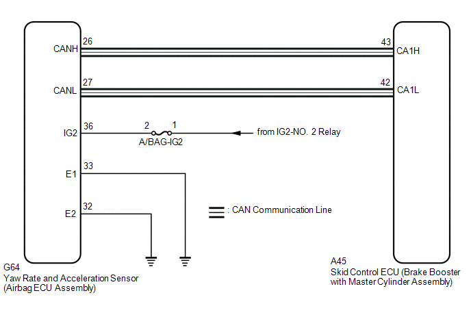
The airbag ECU assembly has a built-in yaw rate and acceleration sensor and detects the vehicle condition using 2 circuits (GL1, GL2).
If a power source malfunction signal from the yaw rate and acceleration sensor (airbag ECU assembly) is detected by the skid control ECU (brake booster with master cylinder assembly), DTC C1381 is stored.
DTC C1381 may be stored due to an intermittent low power source voltage.
| DTC No. | Detection Item | INF Code | DTC Detection Condition | Trouble Area | MIL | Note |
|---|---|---|---|---|---|---|
| C1381 | Abnormal Power Supply Voltage in Yaw Rate and/or Deceleration Sensor | 601 | At a vehicle speed of more than 3 km/h (2 mph), the acceleration sensor power source malfunction signal is received for 10 seconds or more. |
| Comes on |
|
MONITOR DESCRIPTION
The skid control ECU (brake booster with master cylinder assembly) receives valid or invalid information from the yaw rate and acceleration sensor (airbag ECU assembly) power supply voltage via CAN communication. When the vehicle is being driven and an invalid yaw rate and acceleration sensor (airbag ECU assembly) power supply voltage is received via CAN communication for a certain amount of time, the skid control ECU (brake booster with master cylinder assembly) judges that the power supply of the yaw rate and acceleration sensor (airbag ECU assembly) is abnormal and illuminates the MIL and stores this DTC.
MONITOR STRATEGY
| Related DTCs | C14D7: Acceleration sensor voltage circuit/open |
| Required Sensors/Components(Main) | Yaw rate and acceleration sensor (airbag ECU assembly) |
| Required Sensors/Components(Related) | Skid control ECU (brake booster with master cylinder assembly) Speed sensor |
| Frequency of Operation | Continuous |
| Duration | 10 seconds |
| MIL Operation | Immediately |
| Sequence of Operation | None |
TYPICAL ENABLING CONDITIONS
| Monitor runs whenever the following DTCs are not stored | None |
| All of the following conditions are met | - |
| Lost communication with yaw rate and acceleration sensor (airbag ECU assembly) | Not detected |
| IG1 voltage | Higher than 9.54 V |
| Vehicle speed | Higher than 3 km/h (2 mph) |
TYPICAL MALFUNCTION THRESHOLDS
| Yaw rate and acceleration sensor power supply voltage (IG) invalidation/validation (CAN communication data) | "1" (Invalid) |
COMPONENT OPERATING RANGE
| Both of the following conditions are met | - |
| Lost communication with yaw rate and acceleration sensor (airbag ECU assembly) | Not detected |
| Yaw rate and acceleration sensor power supply voltage (IG) invalidation/validation (CAN communication data) | "0" (Valid) |
CONFIRMATION DRIVING PATTERN
- Connect the Techstream to the DLC3.
- Turn the power switch on (IG).
- Turn the Techstream on.
- Clear the DTCs (even if no DTCs are stored, perform the clear DTC procedure).
- Turn the power switch off.
- Turn the power switch on (READY).
- Turn the Techstream on.
- Drive the vehicle at a speed of 3 km/h (2 mph) or more for 10 seconds or more.
- Enter the following menus: Chassis / ABS/VSC/TRAC / Trouble Codes.
-
Read the DTCs.
HINT:
- If a DTC is output, the system is malfunctioning.
- If a DTC is not output, perform the following procedure.
-
If the DTCs are not output, perform a universal trip and check for permanent DTCs.
Click here
.gif)
HINT:
- If a permanent DTC is output, the system is malfunctioning.
- If no permanent DTCs are output, the system is normal.
WIRING DIAGRAM
CAUTION / NOTICE / HINT
NOTICE:
-
After replacing or reinstalling the yaw rate and acceleration sensor (airbag ECU assembly), perform yaw rate and acceleration sensor zero point calibration after clearing previously calibrated data.
Click here
- Inspect the fuses for circuits related to this system before performing the following procedure.
PROCEDURE
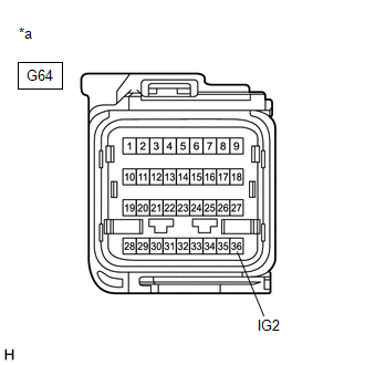
| 1. | CHECK HARNESS AND CONNECTOR (IG2 TERMINAL) |
| (a) Make sure that there is no looseness at the locking part and the connecting part of the connector. OK: The connector is securely connected. |
|
(b) Disconnect the G64 yaw rate and acceleration sensor (airbag ECU assembly) connector.
(c) Check both the connector case and the terminals for deformation and corrosion.
OK:
No deformation or corrosion.
(d) Turn the power switch on (IG).
(e) Measure the voltage according to the value(s) in the table below.
Standard Voltage:
| Tester Connection | Condition | Specified Condition |
|---|---|---|
| G64-36 (IG2) - Body ground | Power switch on (IG) | 11 to 14 V |
| NG |  | REPAIR OR REPLACE HARNESS OR CONNECTOR (IG2 CIRCUIT) |
|

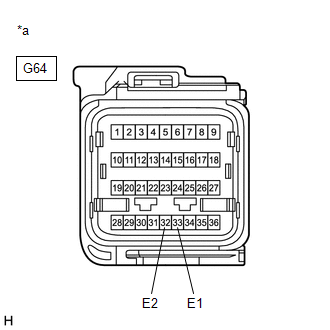
| 2. | CHECK HARNESS AND CONNECTOR (GND TERMINAL) |
| (a) Turn the power switch off. |
|
(b) Measure the resistance according to the value(s) in the table below.
Standard Resistance:
| Tester Connection | Condition | Specified Condition |
|---|---|---|
| G64-33 (E1) - Body ground | Always | Below 1 Ω |
| G64-32 (E2) - Body ground | Always | Below 1 Ω |
| NG | | REPAIR OR REPLACE HARNESS OR CONNECTOR (GND CIRCUIT) |
|
| 3. | RECONFIRM DTC |
(a) Reconnect the G64 yaw rate and acceleration sensor (airbag ECU assembly) connector.
(b) Clear the DTCs.
Click here
(c) Turn the power switch off.
(d) Turn the power switch on (READY).
(e) Perform a road test.
(f) Check if the same DTC is output.
Click here
| Result | Proceed to |
|---|---|
| DTC C1381 is not output. | A |
| DTC C1381 is output. | B |
| A | | USE SIMULATION METHOD TO CHECK |
| B | | REPLACE AIRBAG ECU ASSEMBLY |
READ NEXT:
 Abnormal Leak in Accumulator (C1391)
DESCRIPTION This DTC is stored if internal or external brake fluid leaks are detected due to improper sealing in the brake actuator (brake booster with master cylinder assembly) or brake booster pump
Malfunction in Front Speed Sensor RH Circuit (C1401,C1402)
DESCRIPTION Refer to DTCs C1413 and C1414. Click here DTC No. Detection Item INF Code DTC Detection Condition Trouble Area MIL Note C1401 Malfunction in Front Speed Sensor RH Ci
Malfunction in Rear Speed Sensor RH Circuit (C1403,C1404)
DESCRIPTION Refer to DTCs C1415 and C1416. Click here DTC No. Detection Item INF Code DTC Detection Condition Trouble Area MIL Note C1403 Malfunction in Rear Speed Sensor RH Cir
SEE MORE:
Inspection
INSPECTION PROCEDURE 1. INSPECT BRAKE VACUUM CHECK VALVE ASSEMBLY (a) Check that there is ventilation from the booster side to the engine side, and no ventilation from the engine side to the booster side of the brake vacuum check valve assembly. HINT: If the result is not as specified, replace th
CAN Communication Failure (Message Registry) (U1000)
DESCRIPTION If DTC U1000 is stored frequently, duplicate the conditions that cause the problem symptoms and perform troubleshooting again even if the DTC is not output when rechecking for DTCs. DTC No. Detection Item DTC Detection Condition Trouble Area U1000 CAN Communication Failure
