Lexus ES: Back-up Light Circuit
DESCRIPTION
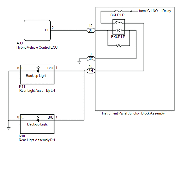
The hybrid vehicle control ECU controls the back-up lights via the BKUP LP relay.
WIRING DIAGRAM
CAUTION / NOTICE / HINT
NOTICE:
- Inspect the fuses for circuits related to this system before performing the following procedure.
-
Before replacing the hybrid vehicle control ECU, refer to Registration.
Click here
.gif)
PROCEDURE
| 1. | CHECK FOR DTC |
(a) Connect the Techstream to the DLC3.
(b) Turn the power switch on (IG).
(c) Turn the Techstream on.
(d) Enter the following menus: Powertrain / Hybrid Control / Trouble Codes.
(e) Check for DTCs.
Powertrain > Hybrid Control > Trouble Codes| Result | Proceed to |
|---|---|
| Hybrid control system DTCs are not output | A |
| Hybrid control system DTCs are output | B |
| B | .gif) | GO TO HYBRID CONTROL SYSTEM |
|
.gif)
| 2. | CHECK HARNESS AND CONNECTOR (INSTRUMENT PANEL JUNCTION BLOCK ASSEMBLY - BODY GROUND) |
(a) Disconnect the 3D instrument panel junction block assembly connector.
(b) Measure the resistance according to the value(s) in the table below.
Standard Resistance:
| Tester Connection | Condition | Specified Condition |
|---|---|---|
| 3D-3 - Body ground | Always | Below 1 Ω |
| NG | | REPAIR OR REPLACE HARNESS OR CONNECTOR |
|
| 3. | CHECK HARNESS AND CONNECTOR (HYBRID VEHICLE CONTROL ECU - INSTRUMENT PANEL JUNCTION BLOCK ASSEMBLY) |
(a) Disconnect the A33 hybrid vehicle control ECU connector.
(b) Disconnect the 3F instrument panel junction block assembly connector.
(c) Measure the resistance according to the value(s) in the table below.
Standard Resistance:
| Tester Connection | Condition | Specified Condition |
|---|---|---|
| A33-2 (BL) - 3F-19 | Always | Below 1 Ω |
| A33-2 (BL) or 3F-19 - Body ground | Always | 10 kΩ or higher |
| NG | | REPAIR OR REPLACE HARNESS OR CONNECTOR |
|
| 4. | CHECK HYBRID VEHICLE CONTROL ECU (OUTPUT VOLTAGE) |
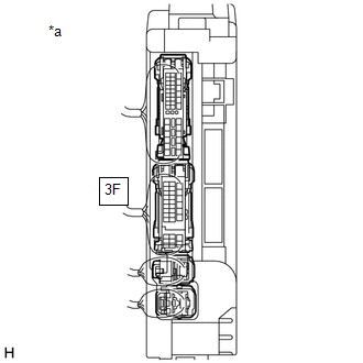
| *a | Component with harness connected (Instrument Panel Junction Block Assembly) |
(a) Connect the A33 hybrid vehicle control ECU connector.
(b) Connect the 3D and 3F instrument panel junction block assembly connectors.
(c) Measure the voltage according to the value(s) in the table below.
Standard Voltage:
| Tester Connection | Condition | Specified Condition |
|---|---|---|
| 3F-19 - Body ground | Power switch off, reverse (R) not selected | Below 1 V |
| 3F-19 - Body ground | Power switch on (IG), reverse (R) selected | 11 to 14 V |
| NG | | REPLACE HYBRID VEHICLE CONTROL ECU |
|
| 5. | INSPECT INSTRUMENT PANEL JUNCTION BLOCK ASSEMBLY (OUTPUT VOLTAGE) |
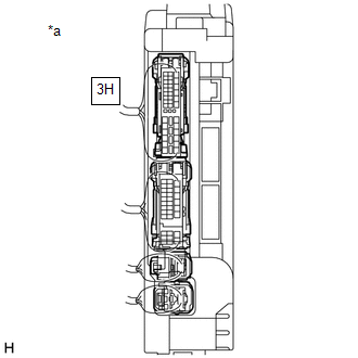
| *a | Component with harness connected (Instrument Panel Junction Block Assembly) |
(a) Measure the voltage according to the value(s) in the table below.
Standard Voltage:
| Tester Connection | Condition | Specified Condition |
|---|---|---|
| 3H-10 - Body ground | Power switch off, reverse (R) not selected | Below 1 V |
| 3H-10 - Body ground | Power switch on (IG), reverse (R) selected | 11 to 14 V |
| OK | | REPAIR OR REPLACE HARNESS OR CONNECTOR |
| NG | | REPLACE INSTRUMENT PANEL JUNCTION BLOCK ASSEMBLY |
READ NEXT:
 Back-up Light Circuit
DESCRIPTION The hybrid vehicle control ECU controls the back-up lights via the BKUP LP relay. WIRING DIAGRAM CAUTION / NOTICE / HINT NOTICE:
Inspect the fuses for circuits related to this system b
Outside Handle Foot Light Circuit
DESCRIPTION The main body ECU (multiplex network body ECU) controls the outside handle foot lights. WIRING DIAGRAM CAUTION / NOTICE / HINT NOTICE: Before replacing the main body ECU (multiplex networ
Front Side Marker Light Circuit
DESCRIPTION When the light control switch is in the tail or head position, the main body ECU (multiplex network body ECU) sends an illumination request signal to the headlight ECU sub-assembly to illu
SEE MORE:
Reassembly
REASSEMBLY PROCEDURE 1. INSTALL SOLENOID (SL) VALVE (a) Coat the solenoid (SL) valve with Toyota Genuine ATF WS. (b) Install the solenoid (SL) valve to the transmission valve body assembly with the bolt. Torque: 7.0 N·m {71 kgf·cm, 62 in·lbf} 2. INSTALL SOLENOID (SLT) VALVE (a)
Vehicle Information Unmatched (C168D)
DESCRIPTION
This DTC is stored if the parking assist ECU judges as a result of its self check that the vehicle information received via CAN communication and the vehicle information stored in the parking assist ECU do not match.
This DTC is stored if the rear television camera assembly judges a
