Lexus ES: Air Conditioning Filter
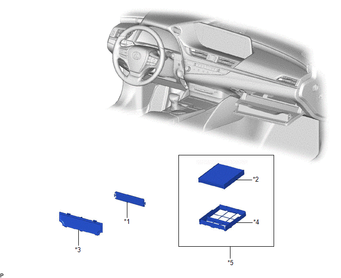
Components
COMPONENTS
ILLUSTRATION
|
*1 |
AIR FILTER COVER PLATE |
*2 |
CLEAN AIR FILTER |
|
*3 |
LOWER INSTRUMENT COVER |
*4 |
AIR FILTER CASE |
|
*5 |
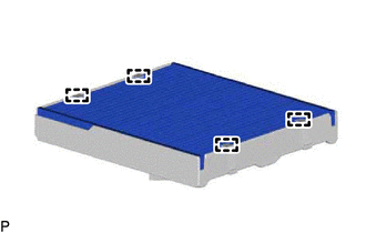
AIR FILTER SUB-ASSEMBLY |
- |
- |
Removal
REMOVAL
PROCEDURE
1. REMOVE LOWER INSTRUMENT COVER
(a) Open the glove compartment door sub-assembly.
(b) Disengage the 2 claws and 4 guides to remove the lower instrument cover as shown in the illustration.
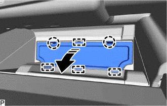
.png) |
Remove in this Direction |
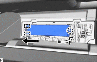
2. REMOVE AIR FILTER COVER PLATE
(a) Disengage the claw and 2 guides as shown in the illustration to remove the air filter cover plate.
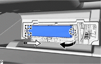
|
|
Remove in this Direction (1) |
 |
Remove in this Direction (2) |
3. REMOVE CLEAN AIR FILTER
(a) Remove the air filter sub-assembly as shown in the illustration.
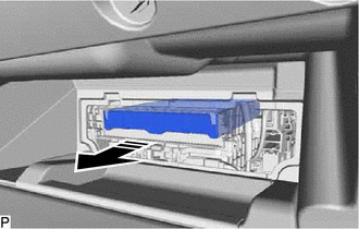
|
|
Remove in this Direction |
|
(b) Disengage the 4 guides to remove the clean air filter from the air filter case. |
|
Installation
INSTALLATION
PROCEDURE
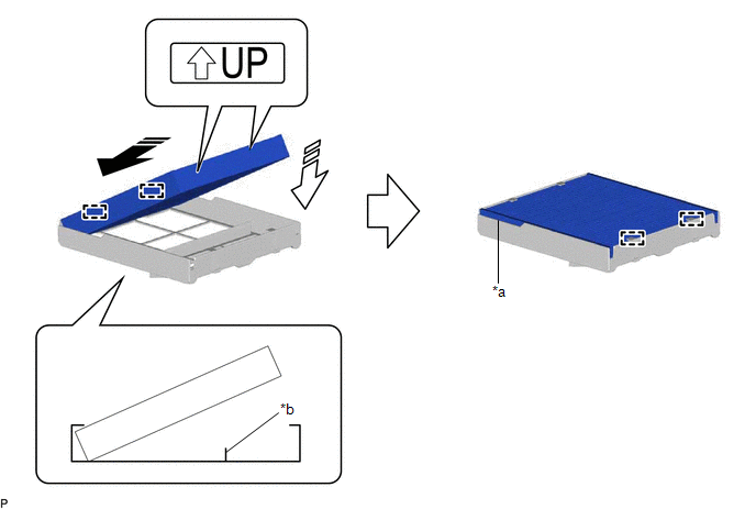
1. INSTALL CLEAN AIR FILTER
(a) Engage the 2 guides on the cutout side of the air filter case and then engage the 2 guides as shown in the illustration to install the clean air filter.
|
*a |
Cutout |
*b |
Rib |
.png) |
Install in this Direction (1) |
.png) |
Install in this Direction (2) |
NOTICE:
- Make sure that the "UP" marks are facing the correct direction before installing the clean air filter.
- Make sure that there is no clearance between the clean air filter and air filter case and that the clean air filter is not deformed.
(b) Install the air filter sub-assembly as shown in the illustration.

|
|
Install in this Direction |
NOTICE:
Make sure that the "UP" mark is facing the correct direction before installing the air filter sub-assembly.
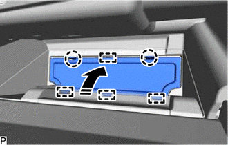
2. INSTALL AIR FILTER COVER PLATE
(a) Engage the 2 guides and claw as shown in the illustration to install the air filter cover plate.
|
|
Install in this Direction (1) |
|
|
Install in this Direction (2) |
3. INSTALL LOWER INSTRUMENT COVER
(a) Engage the 4 guides and 2 claws to install the lower instrument cover as shown in the illustration.
|
|
Install in this Direction |
(b) Close the glove compartment door sub-assembly.
READ NEXT:
 Components
COMPONENTS
ILLUSTRATION
*1
NO. 1 HV BATTERY INTAKE FILTER
*2
BATTERY SERVICE HOLE COVER
Removal
REMOVAL
PROCEDURE
1. REMOVE BATTERY SERVICE HOLE COVER
(a) Remove the clip.
Remove in this Direction
(b) Disengage the 7 claws as shown in the illustration.
(c) Di
SEE MORE:
Radio Broadcast cannot be Received or Poor Reception
CAUTION / NOTICE / HINT NOTICE:
Depending on the parts that are replaced during vehicle inspection or maintenance, performing initialization, registration or calibration may be needed. Refer to Precaution for Navigation System.
Click here
When replacing the radio receiver assembly, always re
Problem Symptoms Table
PROBLEM SYMPTOMS TABLE If there are no DTCs but the problem still occurs, check the suspected areas for each problem symptom in the order given in the table below and proceed to the relevant troubleshooting page. Electronically Controlled Brake System Symptom Suspected Area Link ABS warni
