Lexus ES: GPS Antenna Connection Malfunction(short) (B15C0,B15C1)
DESCRIPTION
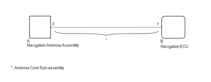
These DTCs are stored when a malfunction occurs in the navigation antenna assembly.
| DTC No. | Detection Item | DTC Detection Condition | Trouble Area |
|---|---|---|---|
| B15C0 | GPS Antenna Connection Malfunction(short) | GPS Antenna Connection Malfunction (short) |
|
| B15C1 | GPS Antenna Connection Malfunction(break) | GPS Antenna Connection Malfunction (break) |
|
WIRING DIAGRAM
CAUTION / NOTICE / HINT
NOTICE:
- Depending on the parts that are replaced during vehicle inspection or maintenance, performing initialization, registration or calibration may be needed. Refer to Precaution for Navigation System.
-
When replacing the navigation ECU, always replace it with a new one. If a navigation ECU which was installed to another vehicle is used, the following may occur:
- A communication malfunction DTC may be stored.
- The navigation ECU may not operate normally.
PROCEDURE
| 1. | CHECK DTC |
(a) Clear the DTCs.
Body Electrical > Navigation System > Clear DTCs(b) Recheck for DTCs and check that no DTCs are output.
Body Electrical > Navigation System > Trouble CodesOK:
No DTCs are output.
| OK |  | USE SIMULATION METHOD TO CHECK |
|

| 2. | INSPECT ANTENNA CORD SUB-ASSEMBLY |
(a) Remove the antenna cord sub-assembly.
Click here .gif)
(b) Measure the resistance according to the value(s) in the table below.
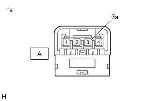
| *a | Component without harness connected (Antenna Cord Sub-assembly) |
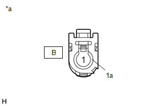
| *a | Component without harness connected (Antenna Cord Sub-assembly) |
Standard Resistance:
| Tester Connection | Condition | Specified Condition |
|---|---|---|
| A-3 - B-1 | Always | Below 1 Ω |
| A-3a - B-1a | Always | Below 1 Ω |
| A-3 or B-1 - Body ground | Always | 10 kΩ or higher |
| A-3a or B-1a - Body ground | Always | 10 kΩ or higher |
| NG | | REPLACE ANTENNA CORD SUB-ASSEMBLY |
|
| 3. | INSPECT NAVIGATION ANTENNA ASSEMBLY |
(a) Remove the navigation antenna assembly.
Click here
(b) Inspect the navigation antenna assembly.
Click here
| OK | | REPLACE NAVIGATION ECU |
| NG | | REPLACE NAVIGATION ANTENNA ASSEMBLY |
READ NEXT:
 Speed Signal Malfunction (B15C2)
DESCRIPTION The navigation ECU receives a vehicle speed signal from the combination meter assembly and information from the navigation antenna assembly, and then adjusts the vehicle position on the ma
Speaker Output Short (B15C3)
DESCRIPTION This DTC is stored when a malfunction occurs in the speakers. DTC No. Detection Item DTC Detection Condition Trouble Area B15C3 Speaker Output Short A short is detected in
MOST Communication Malfunction (B15D0)
DESCRIPTION Navigation system components communicate with each other via MOST communication. If a line short or short to ground occurs in a MOST communication line, communication will not be possible
SEE MORE:
System Too Lean Bank 1 (P017100,P017200,P117000,P117B00)
DESCRIPTION The fuel trim is related to the feedback compensation value, not to the basic injection duration. The fuel trim consists of both the short-term and long-term fuel trims. The short-term fuel trim is fuel compensation that is used to constantly maintain the air fuel ratio at stoichiometric
Crankshaft Position Sensor
ComponentsCOMPONENTS ILLUSTRATION *1 CRANKSHAFT POSITION SENSOR *2 O-RING N*m (kgf*cm, ft.*lbf): Specified torque ● Non-reusable part InstallationINSTALLATION CAUTION / NOTICE / HINT NOTICE: This procedure includes the installation of small-head bolts. Refer to Small-Head
