Lexus ES: Adjustment
ADJUSTMENT
PROCEDURE
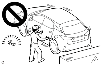
1. SECURE VEHICLE
(a) Fully apply the parking brake and chock a wheel.
CAUTION:
- Make sure to apply the parking brake and chock a wheel before performing this procedure.
- If the vehicle is not secure and the shift lever is moved to N, the vehicle may suddenly move, possibly resulting in an accident or serious injury.
2. INSPECT SHIFT LEVER POSITION SENSOR POSITION
(a) Turn the power switch on (READY).
(b) Move the shift lever to D and release the brake pedal.
CAUTION:
Be sure to apply the parking brake and chock all 4 wheels to secure the vehicle.
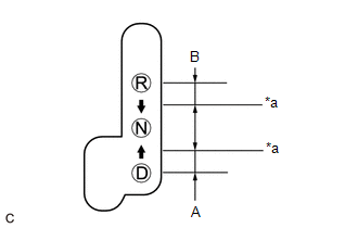
| (c) Slowly move the shift lever to N and measure the moving distance (A) of the shift lever from the original point to the gear disengagement point. NOTICE: Be sure to move the shift lever slowly. |
|
(d) Move the shift lever to R and release the brake.
CAUTION:
Be sure to apply the parking brake and chock all 4 wheels to secure the vehicle.
(e) Slowly move the shift lever to N and measure the moving distance (B) of the shift lever from the original point to the gear disengagement point.
NOTICE:
Be sure to move the shift lever slowly.
(f) Check that the moving distances (A) and (B) shown in the illustration are almost the same.
HINT:
- If the moving distances (A) and (B) are almost the same, adjustment of the shift lever position is not necessary.
- If the moving distance (A) is shorter than (B), perform step [#1] of Adjust Shift Lever Position Sensor Position.
- If the moving distance (B) is shorter than (A), perform step [#2] of Adjust Shift Lever Position Sensor Position.
3. ADJUST SHIFT LEVER POSITION SENSOR POSITION
(a) If the moving distance (A) is shorter than (B). [#1]
HINT:
If the shift lever is moved from R to N, the moving distance of the shift lever from the original point to the gear disengagement point becomes longer.
(1) Move the shift lever to N.
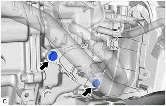
| (2) Loosen the 2 bolts. NOTICE:
|
|
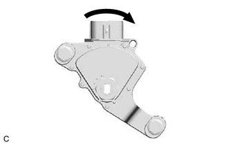
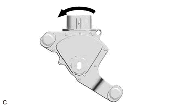
| (3) Slightly turn the shift lever position sensor clockwise. |
|
| (4) Tighten the 2 bolts. Torque: 11 N·m {112 kgf·cm, 8 ft·lbf} |
|
(5) Check the shift lever position sensor position.
(b) If the moving distance (B) is shorter than (A). [#2]
HINT:
If the shift lever is moved from D to N, the moving distance of the shift lever from the original point to the gear disengagement point becomes longer.
(1) Move the shift lever to N.
| (2) Loosen the 2 bolts. NOTICE:
|
|
| (3) Slightly turn the shift lever position sensor counterclockwise. |
|
| (4) Tighten the 2 bolts. Torque: 11 N·m {112 kgf·cm, 8 ft·lbf} |
|
(5) Check the shift lever position sensor position.
READ NEXT:
 Components
COMPONENTS ILLUSTRATION *1 FRONT WHEEL OPENING EXTENSION PAD RH *2 FRONT WHEEL OPENING EXTENSION PAD LH *3 NO. 1 ENGINE UNDER COVER *4 NO. 2 ENGINE UNDER COVER ASSEMBLY N*m
Inspection
INSPECTION PROCEDURE 1. INSPECT SHIFT LEVER POSITION SENSOR (a) Measure the resistance according to the value(s) in the table below. Standard Resistance: Tester Connection Condition Specifi
Installation
INSTALLATION PROCEDURE 1. INSTALL SHIFT LEVER POSITION SENSOR (a) Move the shift lever to N. (b) Clean and degrease the 2 bolt holes of the hybrid vehicle transaxle assembly. (c) Tempor
SEE MORE:
Removal
REMOVAL CAUTION / NOTICE / HINT The necessary procedures (adjustment, calibration, initialization, or registration) that must be performed after parts are removed and installed, or replaced during speaker assembly with bracket removal/installation are shown below. Necessary Procedure After Parts Rem
USB Audio System Recognition/Play Error
DESCRIPTION When a USB device or "iPod" is connected to the USB jack of the No. 1 stereo jack adapter assembly, it must have playable files. The device must also communicate with and be recognized by the radio receiver assembly. This diagnostic procedure is for when a device is not recognized, or fi
