Lexus ES: Replacement
REPLACEMENT
CAUTION / NOTICE / HINT
The necessary procedures (adjustment, calibration, initialization, or registration) that must be performed after parts are removed and installed, or replaced during front drive shaft oil seal LH and front drive shaft oil seal RH removal/installation are shown below.
Necessary Procedures After Parts Removed/Installed/Replaced| Replaced Part or Performed Procedure | Necessary Procedure | Effect/Inoperative Function when Necessary Procedure not Performed | Link |
|---|---|---|---|
| Front wheel alignment adjustment |
|
| |
| Replacement of automatic transaxle fluid | ATF thermal degradation estimate reset | The value of the Data List item "ATF Thermal Degradation Estimate" is not estimated correctly | |
PROCEDURE
1. REMOVE FRONT DRIVE SHAFT ASSEMBLY
Click here .gif)
2. REMOVE DRIVE SHAFT BEARING BRACKET
Click here
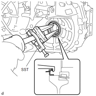
3. REMOVE FRONT DRIVE SHAFT OIL SEAL LH
| (a) Using SST, remove the front drive shaft oil seal LH from the automatic transaxle case sub-assembly. SST: 09308-00010 NOTICE: Be careful not to damage the automatic transaxle case sub-assembly. |
|
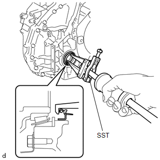
4. REMOVE FRONT DRIVE SHAFT OIL SEAL RH
| (a) Using SST, remove the front drive shaft oil seal RH from the transaxle housing. SST: 09308-00010 NOTICE: Be careful not to damage the transaxle housing. |
|
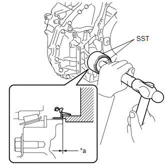
5. INSTALL FRONT DRIVE SHAFT OIL SEAL RH
| (a) Using SST and a hammer, install a new front drive shaft oil seal RH to the transaxle housing. SST: 09316-10010 SST: 09950-70010 09951-07150 Standard Depth: -0.5 to 0.5 mm (-0.0197 to 0.0197 in.) NOTICE:
|
|
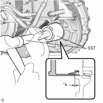
6. INSTALL FRONT DRIVE SHAFT OIL SEAL LH
| (a) Using SST and a hammer, install a new front drive shaft oil seal LH to the automatic transaxle case sub-assembly. SST: 09649-17010 SST: 09950-70010 09951-07100 Standard Depth: -0.5 to 0.5 mm (-0.0197 to 0.0197 in.) NOTICE:
|
|
7. INSTALL DRIVE SHAFT BEARING BRACKET
Click here
8. INSTALL FRONT DRIVE SHAFT ASSEMBLY
Click here
READ NEXT:
 Components
COMPONENTS ILLUSTRATION *A Type A *B Type B *1 FRONT FENDER APRON SEAL LH *2 FRONT WHEEL OPENING EXTENSION PAD LH *3 FRONT WHEEL OPENING EXTENSION PAD RH *4 NO. 1 ENGINE
Installation
INSTALLATION PROCEDURE 1. INSTALL TRANSMISSION OIL COOLER (a) Temporarily install the transmission oil cooler to the automatic transaxle case sub-assembly with the bolt (A). (b) Install
SEE MORE:
Removal
REMOVAL CAUTION / NOTICE / HINT The necessary procedures (adjustment, calibration, initialization, or registration) that must be performed after parts are removed and installed, or replaced during kick door control sensor removal/installation are shown below. Necessary Procedure After Parts Removed/
Fuel Main Valve
ComponentsCOMPONENTS ILLUSTRATION *1 FUEL SUCTION TUBE WITH PUMP AND GAUGE ASSEMBLY *2 FUEL MAIN VALVE ASSEMBLY *3 FUEL PRESSURE REGULATOR HOLDER *4 O-RING ● Non-reusable part - - InstallationINSTALLATION PROCEDURE 1. INSTALL FUEL MAIN VALVE ASSEMBLY (a) Apply ga
