Lexus ES: Wiper Switch Signal Mismatch between LIN and Line (B1372)
DESCRIPTION
Under normal operation, the windshield wiper motor assembly receives operation signals from the windshield wiper switch assembly via LIN communication.
The windshield wiper motor assembly and windshield wiper switch assembly are also connected via direct line in order to operate the front wipers in HI in an emergency. If the operation signals sent via LIN communication and direct line do not match, this DTC is stored.
| DTC No. | Detection Item | DTC Detection Condition | Trouble Area | Memory | DTC Output from |
|---|---|---|---|---|---|
| B1372 | Wiper Switch Signal Mismatch between LIN and Line |
|
| ○ | Wiper |
WIRING DIAGRAM

CAUTION / NOTICE / HINT
NOTICE:
Before replacing the main body ECU (multiplex network body ECU), refer to Registration.
Click here 
PROCEDURE
| 1. | CLEAR DTC |
(a) Connect the Techstream to the DLC3.
(b) Turn the engine switch on (IG).
(c) Turn the Techstream on.
(d) Enter the following menus: Body Electrical / Wiper / Trouble Codes.
(e) Clear the DTCs.
Body Electrical > Wiper > Clear DTCs
|

| 2. | CHECK FOR DTC |
(a) Connect the Techstream to the DLC3.
(b) Turn the engine switch on (IG).
(c) Wait 10 seconds or more.
(d) Turn the Techstream on.
(e) Enter the following menus: Body Electrical / Wiper / Trouble Codes.
(f) Check for DTCs.
Body Electrical > Wiper > Trouble Codes| Result | Proceed to |
|---|---|
| DTC B1372 is not output | A |
| DTC B1372 is output | B |
| A | .gif) | USE SIMULATION METHOD TO CHECK |
|
| 3. | READ VALUE USING TECHSTREAM |
(a) Connect the Techstream to the DLC3.
(b) Turn the engine switch on (IG).
(c) Turn the Techstream on.
(d) Enter the following menus: Body Electrical / Wiper / Data List.
(e) Read the Data List according to the display on the Techstream.
Body Electrical > Wiper > Data List| Tester Display | Measurement Item | Range | Normal Condition | Diagnostic Note |
|---|---|---|---|---|
| Wiper Switch HI (Line) | Front wiper switch HI position signal (direct line) | OFF or ON | OFF: Front wiper switch not in HI position ON: Front wiper switch in HI position | - |
| Tester Display |
|---|
| Wiper Switch HI (Line) |
OK:
The Techstream display is normal.
| NG | | GO TO STEP 7 |
|
| 4. | READ VALUE USING TECHSTREAM |
(a) Connect the Techstream to the DLC3.
(b) Turn the engine switch on (IG).
(c) Turn the Techstream on.
(d) Enter the following menus: Chassis / Steering Angle Sensor / Data List.
(e) Read the Data List according to the display on the Techstream.
Chassis > Steering Angle Sensor > Data List| Tester Display | Measurement Item | Range | Normal Condition | Diagnostic Note |
|---|---|---|---|---|
| Wiper Hi Switch | Front wiper switch HI position signal | OFF or ON | OFF: Front wiper switch not in HI position ON: Front wiper switch in HI position | - |
| Tester Display |
|---|
| Wiper Hi Switch |
OK:
The Techstream display is normal.
| NG | | REPLACE STEERING SENSOR |
|
| 5. | CHECK HARNESS AND CONNECTOR (MAIN BODY ECU (MULTIPLEX NETWORK BODY ECU) - WINDSHIELD WIPER MOTOR ASSEMBLY) |
(a) Disconnect the G36 main body ECU (multiplex network body ECU) connector.
(b) Disconnect the A38 windshield wiper motor assembly connector.
(c) Measure the resistance according to the value(s) in the table below.
Standard Resistance:
| Tester Connection | Condition | Specified Condition |
|---|---|---|
| G36-3 (LIN3) - A38-2 (LIN) | Always | Below 1 Ω |
| G36-3 (LIN3) or A38-2 (LIN) - Body ground | Always | 10 kΩ Higher |
| NG | | REPAIR OR REPLACE HARNESS OR CONNECTOR |
|
| 6. | CHECK MAIN BODY ECU (MULTIPLEX NETWORK BODY ECU) |
.png)
| *a | Component without harness connected (Main Body ECU (Multiplex Network Body ECU) |
(a) Check for voltage and pulses according to the value(s) in the table below.
Standard Voltage:
| Tester Connection | Condition | Specified Condition |
|---|---|---|
| G36-3 (LIN3) - Body ground | Engine switch off | Below 1 V |
| Engine switch on (IG) | Pulse generation |
| OK | | REPLACE WINDSHIELD WIPER MOTOR ASSEMBLY |
| NG | | REPLACE MAIN BODY ECU (MULTIPLEX NETWORK BODY ECU) |
| 7. | CHECK HARNESS AND CONNECTOR (STEERING SENSOR - WINDSHIELD WIPER MOTOR ASSEMBLY) |
(a) Disconnect the G62 steering sensor connector.
(b) Disconnect the A38 windshield wiper motor assembly connector.
(c) Measure the resistance according to the value(s) in the table below.
Standard Resistance:
| Tester Connection | Condition | Specified Condition |
|---|---|---|
| G62-2 (2S) - A38-3 (2S) | Always | Below 1 Ω |
| G62-2 (2S) or A38-3 (2S) - Body ground | Always | 10 kΩ Higher |
| NG | | REPAIR OR REPLACE HARNESS OR CONNECTOR |
|
| 8. | INSPECT STEERING SENSOR |
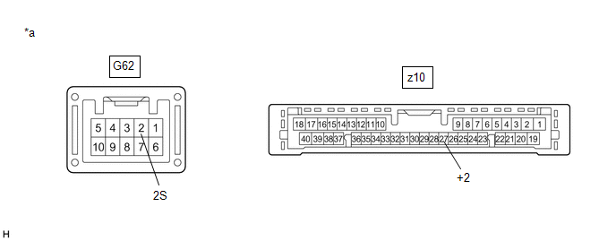
| *a | Component without harness connected (Steering Sensor) | - | - |
(a) Remove the steering sensor.
Click here
(b) Measure the resistance according to the value(s) in the table below.
Standard Resistance:
| Tester Connection | Condition | Specified Condition |
|---|---|---|
| G62-2 (2S) - z10-27 (+2) | Always | Below 1 Ω |
| OK | | REPLACE WINDSHIELD WIPER MOTOR ASSEMBLY |
| NG | | REPLACE STEERING SENSOR |
READ NEXT:
 Lost Communication with Wiper System LIN BUS (B1373)
DESCRIPTION The main body ECU (multiplex network body ECU) and windshield wiper motor assembly communicate via LIN communication. The main body ECU (multiplex network body ECU) stores this DTC if comm
Rain Sensor Malfunction (B1400)
DESCRIPTION This DTC is stored when the rain sensor detects an internal malfunction. DTC No. Detection Item DTC Detection Condition Trouble Area Memory DTC Output from B1400 Rain Se
Wiper Motor Power Source Circuit
DESCRIPTION This circuit is the power source circuit for the windshield wiper motor assembly. WIRING DIAGRAM CAUTION / NOTICE / HINT NOTICE:
Inspect the fuses of circuits related to this system be
SEE MORE:
Terminals Of Ecu
TERMINALS OF ECU CHECK INSTRUMENT PANEL JUNCTION BLOCK ASSEMBLY AND MAIN BODY ECU (MULTIPLEX NETWORK BODY ECU) (a) Remove the main body ECU (multiplex network body ECU) from the instrument panel junction block assembly. Click here (b) Measure the resistance according to the value(s) in the table
Installation
INSTALLATION PROCEDURE 1. INSTALL NO. 2 FUEL SENDER GAUGE ASSEMBLY (a) Engage the claw to install the No. 2 fuel sender gauge assembly to the fuel tank vent tube assembly. NOTICE: Be careful not to bend the arm of the No. 2 fuel sender gauge assembly. (b) Engage the 2 clamps to connect the wire harn
