Lexus ES: Voice Guidance does not Function
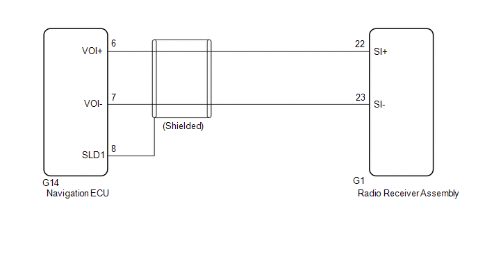
WIRING DIAGRAM
PROCEDURE
| 1. | CHECK VOICE GUIDANCE SETTING |
(a) Check that the voice guidance settings are not off.
OK:
Voice guidance settings are not off.
| NG | .gif) | CHANGE VOICE GUIDANCE SETTINGS TO ON |
|
.gif)
| 2. | CHECK HARNESS AND CONNECTOR (RADIO RECEIVER ASSEMBLY - NAVIGATION ECU) |
(a) Disconnect the G1 radio receiver assembly connector.
(b) Disconnect the G14 navigation ECU connector.
(c) Measure the resistance according to the value(s) in the table below.
Standard Resistance:
| Tester Connection | Condition | Specified Condition |
|---|---|---|
| G1-22 (SI+) - G14-6 (VOI+) | Always | Below 1 Ω |
| G1-23 (SI-) - G14-7 (VOI-) | Always | Below 1 Ω |
| G1-22 (SI+) or G14-6 (VOI+) - Body ground | Always | 10 kΩ or higher |
| G1-23 (SI-) or G14-7 (VOI-) - Body ground | Always | 10 kΩ or higher |
| G14-8 (SLD1) - Body ground | Always | 10 kΩ or higher |
| OK | | PROCEED TO NEXT SUSPECTED AREA SHOWN IN PROBLEM SYMPTOMS TABLE |
.gif)
| NG | | REPAIR OR REPLACE HARNESS OR CONNECTOR |
READ NEXT:
 Voice is not Recognized
PROCEDURE 1. CHECK CONDITION (a) While paying attention to the condition of the spoken voice command, perform a voice recognition operation. OK: Voice command is recognized normally. HINT:
Weather and traffic information cannot be obtained
CAUTION / NOTICE / HINT NOTICE:
Depending on the parts that are replaced during vehicle inspection or maintenance, performing initialization, registration or calibration may be needed. Refer to Pre
SEE MORE:
Definition Of Terms
DEFINITION OF TERMS Term Definition Monitor description Description of what the ECM monitors and how it detects malfunctions (monitoring purpose and details). Related DTCs Group of diagnostic trouble codes that are output by the ECM based on the same malfunction detection logic.
Installation
INSTALLATION CAUTION / NOTICE / HINT HINT:
Use the same procedure for the RH side and LH side.
The following procedure is for the LH side.
PROCEDURE 1. INSTALL WASHER NOZZLE SUB-ASSEMBLY (a) Connect a new washer nozzle sub-assembly to the washer hose. (b) Engage the 2 claws as indicated by t
