Lexus ES: Visual Mute Signal Circuit between Radio Receiver and Multi-display
DESCRIPTION
The radio receiver assembly sends a visual mute signal to the multi-display assembly. As a result, a black screen is displayed when the screen changes so that noise and distorted images are not displayed.
When an open exists in the circuit, noise and distorted images will be displayed instead of a black screen.
When a short exists in the circuit, even though the multi-display assembly is operating normally, noise and distorted images will be displayed (black screen will not be displayed) during screen changes or the black screen will always be displayed.
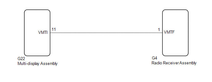
WIRING DIAGRAM
CAUTION / NOTICE / HINT
NOTICE:
-
Depending on the parts that are replaced during vehicle inspection or maintenance, performing initialization, registration or calibration may be needed. Refer to Precaution for Audio and Visual System.
Click here
.gif)
-
When replacing the radio receiver assembly, always replace it with a new one. If a radio receiver assembly which was installed to another vehicle is used, the following may occur:
- A communication malfunction DTC may be stored.
- The radio receiver assembly may not operate normally.
PROCEDURE
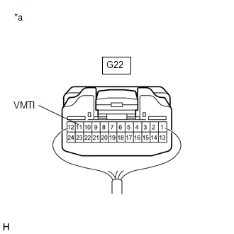
| 1. | INSPECT MULTI-DISPLAY ASSEMBLY |
| (a) Measure the voltage according to the value(s) in the table below. Standard Voltage:
|
|
| OK |  | PROCEED TO NEXT SUSPECTED AREA SHOWN IN PROBLEM SYMPTOMS TABLE |
|

| 2. | CHECK HARNESS AND CONNECTOR (RADIO RECEIVER ASSEMBLY - MULTI-DISPLAY ASSEMBLY) |
(a) Disconnect the G22 multi-display assembly connector.
(b) Disconnect the G4 radio receiver assembly connector.
(c) Measure the resistance according to the value(s) in the table below.
Standard Resistance:
| Tester Connection | Condition | Specified Condition |
|---|---|---|
| G4-1 (VMTF) - G22-11 (VMTI) | Always | Below 1 Ω |
| G4-1 (VMTF) or G22-11 (VMTI) - Body ground | Always | 10 kΩ or higher |
| NG | | REPAIR OR REPLACE HARNESS OR CONNECTOR |
|
| 3. | REPLACE MULTI-DISPLAY ASSEMBLY |
(a) Replace the multi-display assembly with a new or known good one.
Click here
(b) Check that the screen display is normal.
OK:
Screen display is normal.
| OK | | END |
| NG | | REPLACE RADIO RECEIVER ASSEMBLY |
READ NEXT:
 Voice Guidance Circuit between Radio Receiver and Stereo Component Amplifier
DESCRIPTION Using this circuit, the radio receiver assembly sends signals to the stereo component amplifier assembly. WIRING DIAGRAM PROCEDURE 1. CHECK HARNESS AND CONNECTOR (RADIO RECEIVER ASS
Voice Guidance does not Function
CAUTION / NOTICE / HINT NOTICE:
Depending on the parts that are replaced during vehicle inspection or maintenance, performing initialization, registration or calibration may be needed. Refer to Pre
Voice is not Recognized
PROCEDURE 1. CHECK CONDITION (a) While paying attention to the condition of the spoken voice command, perform a voice recognition operation. OK: Voice command is recognized normally. HINT:
SEE MORE:
BSM Buzzer Sound Request Signal Malfunction (C2A5C)
DESCRIPTION This DTC is stored when the rear television camera assembly receives an invalid communication signal from the blind spot monitor sensor RH. DTC No. Detection Item DTC Detection Condition Trouble Area C2A5C BSM Buzzer Sound Request Signal Malfunction An invalid communicat
Terminals Of Ecu
TERMINALS OF ECU CHECK VEHICLE APPROACHING SPEAKER CONTROLLER (a) Disconnect the G42 vehicle approaching speaker controller connector. (b) Measure the voltage and resistance according to the value(s) in the table below. Terminal No. (Symbol) Wiring Color Terminal Description Condition Sp
