Lexus ES: Voice Guidance Circuit between Radio Receiver and Stereo Component Amplifier
DESCRIPTION
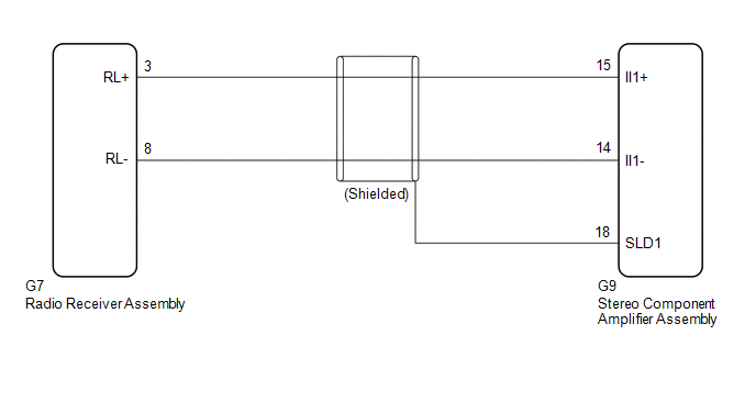
Using this circuit, the radio receiver assembly sends signals to the stereo component amplifier assembly.
WIRING DIAGRAM
PROCEDURE
| 1. | CHECK HARNESS AND CONNECTOR (RADIO RECEIVER ASSEMBLY - STEREO COMPONENT AMPLIFIER ASSEMBLY) |
(a) Disconnect the G7 radio receiver assembly connector.
(b) Disconnect the G9 stereo component amplifier assembly connector.
(c) Measure the resistance according to the value(s) in the table below.
Standard Resistance:
| Tester connection | Condition | Specified condition |
|---|---|---|
| G7-3 (RL+) - G9-15 (II1+) | Always | Below 1 Ω |
| G7-8 (RL-) - G9-14 (II1-) | Always | Below 1 Ω |
| G9-18 (SLD1) - Body ground | Always | 10 kΩ or higher |
| G7-3 (RL+) or G9-15 (II1+) - Body ground | Always | 10 kΩ or higher |
| G7-8 (RL-) or G9-14 (II1-) - Body ground | Always | 10 kΩ or higher |
| OK |  | PROCEED TO NEXT SUSPECTED AREA SHOWN IN PROBLEM SYMPTOMS TABLE |
.gif)
| NG | | REPAIR OR REPLACE HARNESS OR CONNECTOR |
READ NEXT:
 Voice Guidance does not Function
CAUTION / NOTICE / HINT NOTICE:
Depending on the parts that are replaced during vehicle inspection or maintenance, performing initialization, registration or calibration may be needed. Refer to Pre
Voice is not Recognized
PROCEDURE 1. CHECK CONDITION (a) While paying attention to the condition of the spoken voice command, perform a voice recognition operation. OK: Voice command is recognized normally. HINT:
SEE MORE:
Remote Control System does not Operate
DESCRIPTION The main body ECU (multiplex network body ECU) receives remote control signals from the driver door key cylinder or electrical key transmitter sub-assembly. Then, the main body ECU (multiplex network body ECU) activates the power window motor and sends the remote control signals to the s
Problem Symptoms Table
PROBLEM SYMPTOMS TABLE HINT:
Use the table below to help determine the cause of problem symptoms. If multiple suspected areas are listed, the potential causes of the symptoms are listed in order of probability in the "Suspected Area" column of the table.
Check each symptom by checking the suspe
