Lexus ES: Vehicle Speed Signal Circuit between Navigation ECU and Combination Meter
DESCRIPTION
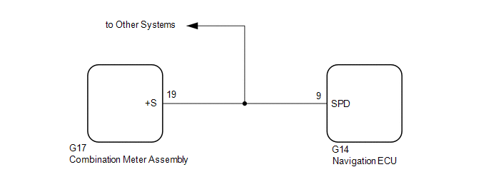
The navigation ECU receives a vehicle speed signal from the combination meter assembly.
HINT:
- A voltage of 12 V or 5 V is output from each ECU and then input to the combination meter assembly. The signal is changed to a pulse signal at the transistor in the combination meter assembly. Each ECU controls its respective systems based on this pulse signal.
- If a short occurs in any of the ECUs or in the wire harness connected to an ECU, all systems in the following diagram will not operate normally.
WIRING DIAGRAM
PROCEDURE
| 1. | CHECK COMBINATION METER ASSEMBLY (OUTPUT WAVEFORM) |
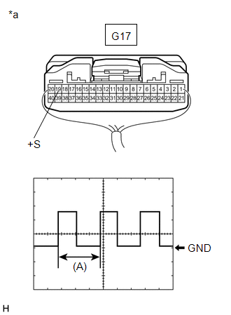
| (a) Check the output waveform. (1) Remove the combination meter assembly with the connector still connected. (2) Connect an oscilloscope to terminal G17-19 (+S) and body ground. (3) Turn the engine switch on (IG). (4) Turn a wheel slowly. (5) Check the signal waveform according to the condition(s) in the table below.
OK: The waveform is similar to that shown in the illustration. HINT: When the system is functioning normally, one wheel revolution generates 4 pulses. As the vehicle speed increases, the width indicated by (A) in the illustration narrows. |
|
| NG |  | GO TO METER / GAUGE SYSTEM |
.gif)
|

| 2. | INSPECT NAVIGATION ECU (INPUT WAVEFORM) |
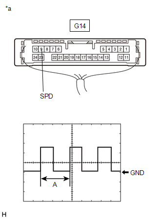
| (a) Check the input waveform. (1) Remove the navigation ECU with the connector(s) still connected. (2) Connect an oscilloscope to terminal G14-9 (SPD) and body ground. (3) Turn the engine switch on (IG). (4) Turn a wheel slowly. (5) Check the signal waveform according to the condition(s) in the table below.
OK: The waveform is similar to that shown in the illustration. HINT: When the system is functioning normally, one wheel revolution generates 4 pulses. As the vehicle speed increases, the width indicated by (A) in the illustration narrows. |
|
| OK | | PROCEED TO NEXT SUSPECTED AREA SHOWN IN PROBLEM SYMPTOMS TABLE |
| NG | | REPAIR OR REPLACE HARNESS OR CONNECTOR |
READ NEXT:
 Vehicle Speed Signal Circuit between Stereo Component Amplifier and Combination Meter
DESCRIPTION The stereo component amplifier assembly receives a vehicle speed signal from the combination meter assembly to control the ASL function. HINT:
A voltage of 12 V or 5 V is output from ea
Visual Mute Signal Circuit between Radio Receiver and Multi-display
DESCRIPTION The radio receiver assembly sends a visual mute signal to the multi-display assembly. As a result, a black screen is displayed when the screen changes so that noise and distorted images ar
Voice Guidance does not Function
WIRING DIAGRAM PROCEDURE 1. CHECK VOICE GUIDANCE SETTING (a) Check that the voice guidance settings are not off. OK: Voice guidance settings are not off. NG CHANGE VOICE GUIDANCE SETT
SEE MORE:
Components
COMPONENTS ILLUSTRATION *1 NO. 1 ENGINE UNDER COVER *2 NO. 2 ENGINE UNDER COVER ASSEMBLY *3 FRONT WHEEL OPENING EXTENSION PAD LH *4 FRONT WHEEL OPENING EXTENSION PAD RH *5 FRONT FENDER APRON SEAL LH - - N*m (kgf*cm, ft.*lbf): Specified torque - - ILLUSTRAT
Vehicle Information Unmatched (C168D)
DESCRIPTION This DTC is stored if the rear television camera assembly judges as a result of its self check that the vehicle information received from the main body ECU (multiplex network body ECU) via CAN communication and the vehicle information stored in the rear television camera assembly do not
