Lexus ES: Visual Mute Signal Circuit between Radio Receiver and Multi-display
DESCRIPTION
The radio receiver assembly sends a visual mute signal to the multi-display assembly. As a result, a black screen is displayed when the screen changes so that noise and distorted images are not displayed.
When an open exists in the circuit, noise and distorted images will be displayed instead of a black screen.
When a short exists in the circuit, even though the multi-display assembly is operating normally, noise and distorted images will be displayed (black screen will not be displayed) during screen changes or the black screen will always be displayed.
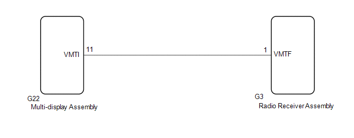
WIRING DIAGRAM
CAUTION / NOTICE / HINT
NOTICE:
-
Depending on the parts that are replaced during vehicle inspection or maintenance, performing initialization, registration or calibration may be needed. Refer to Precaution for Navigation System.
Click here
.gif)
-
When replacing the radio receiver assembly, always replace it with a new one. If a radio receiver assembly which was installed to another vehicle is used, the following may occur:
- A communication malfunction DTC may be stored.
- The radio receiver assembly may not operate normally.
PROCEDURE
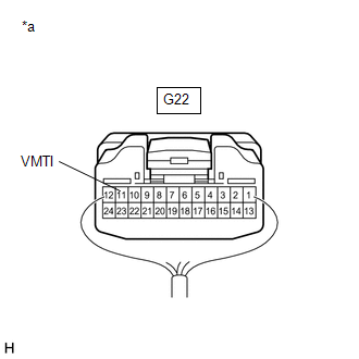
| 1. | INSPECT MULTI-DISPLAY ASSEMBLY |
| (a) Measure the voltage according to the value(s) in the table below. Standard Voltage:
|
|
| OK |  | PROCEED TO NEXT SUSPECTED AREA SHOWN IN PROBLEM SYMPTOMS TABLE |
|

| 2. | CHECK HARNESS AND CONNECTOR (RADIO RECEIVER ASSEMBLY - MULTI-DISPLAY ASSEMBLY) |
(a) Disconnect the G22 multi-display assembly connector.
(b) Disconnect the G3 radio receiver assembly connector.
(c) Measure the resistance according to the value(s) in the table below.
Standard Resistance:
| Tester Connection | Condition | Specified Condition |
|---|---|---|
| G3-1 (VMTF) - G22-11 (VMTI) | Always | Below 1 Ω |
| G3-1 (VMTF) or G22-11 (VMTI) - Body ground | Always | 10 kΩ or higher |
| NG | | REPAIR OR REPLACE HARNESS OR CONNECTOR |
|
| 3. | REPLACE MULTI-DISPLAY ASSEMBLY |
(a) Replace the multi-display assembly with a new or known good one.
Click here
(b) Check that the screen display is normal.
OK:
Screen display is normal.
| OK | | END |
| NG | | REPLACE RADIO RECEIVER ASSEMBLY |
READ NEXT:
 Voice Guidance does not Function
WIRING DIAGRAM PROCEDURE 1. CHECK VOICE GUIDANCE SETTING (a) Check that the voice guidance settings are not off. OK: Voice guidance settings are not off. NG CHANGE VOICE GUIDANCE SETT
Voice is not Recognized
PROCEDURE 1. CHECK CONDITION (a) While paying attention to the condition of the spoken voice command, perform a voice recognition operation. OK: Voice command is recognized normally. HINT:
Weather and traffic information cannot be obtained
CAUTION / NOTICE / HINT NOTICE:
Depending on the parts that are replaced during vehicle inspection or maintenance, performing initialization, registration or calibration may be needed. Refer to Pre
SEE MORE:
Refueling
Opening the fuel tank cap
The fuel tank of your vehicle has a
special structure, which requires a
reduction in fuel tank pressure
before refueling. After the opener
switch has been pressed, it will take
several seconds until the vehicle is
ready for refueling.
Before refueling the vehicle
Cold Start Idle Control System Performance (P050A00)
MONITOR DESCRIPTION This monitor will run when the engine is started at an engine coolant temperature of -10 to 50°C (14 to 122°F). The DTC will be stored after the engine idles for 13 seconds (2 trip detection logic). The DTC is designed to monitor the idle air control at cold start. When the eng
