Lexus ES: Rear Height Control Sensor (B241A)
DESCRIPTION
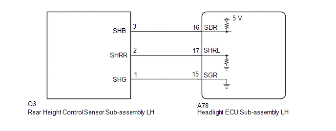
The headlight ECU sub-assembly LH determines the vehicle height and performs automatic headlight beam level control based on signals from the rear height control sensor sub-assembly LH via direct line.
| DTC No. | Detection Item | DTC Detection Condition | Trouble Area | DTC Output from |
|---|---|---|---|---|
| B241A | Rear Height Control Sensor |
|
| AFS |
WIRING DIAGRAM
CAUTION / NOTICE / HINT
NOTICE:
-
If the headlight ECU sub-assembly LH has been replaced, it is necessary to synchronize the vehicle information and initialize the headlight ECU sub-assembly LH.
Click here
.gif)
-
If any of the following are performed, it is necessary to initialize the headlight ECU sub-assembly LH.
Click here
- Replacement of the rear height control sensor sub-assembly LH
- Removal/installation of the rear height control sensor sub-assembly LH
- Work that changes the vehicle height such as replacement of suspension components
- When replacing the headlight ECU sub-assembly LH, always replace it with a new one. If a headlight ECU sub-assembly LH which was installed to another vehicle is used, the information stored in it will not match the information from the vehicle and a DTC may be stored.
PROCEDURE
| 1. | CLEAR DTC |
(a) Connect the Techstream to the DLC3.
(b) Turn the power switch on (IG).
(c) Turn the Techstream on.
(d) Enter the following menus: Body Electrical / AFS / Trouble Codes.
(e) Clear the DTCs.
Body Electrical > AFS > Clear DTCs
|
.gif)
| 2. | CHECK FOR DTC |
(a) Connect the Techstream to the DLC3.
(b) Turn the power switch on (IG).
(c) Wait 10 seconds or more.
(d) Turn the Techstream on.
(e) Enter the following menus: Body Electrical / AFS / Trouble Codes.
(f) Check for DTCs.
Body Electrical > AFS > Trouble CodesOK:
DTC B241A is not output.
| OK | .gif) | USE SIMULATION METHOD TO CHECK |
|
| 3. | INSPECT REAR HEIGHT CONTROL SENSOR SUB-ASSEMBLY LH |
(a) Remove the rear height control sensor sub-assembly LH.
Click here
(b) Inspect the rear height control sensor sub-assembly LH.
Click here
| NG | | REPLACE REAR HEIGHT CONTROL SENSOR SUB-ASSEMBLY LH |
|
| 4. | CHECK HARNESS AND CONNECTOR (REAR HEIGHT CONTROL SENSOR SUB-ASSEMBLY LH - HEADLIGHT ECU SUB-ASSEMBLY LH) |
(a) Disconnect the A78 headlight ECU sub-assembly LH connector.
(b) Measure the resistance according to the value(s) in the table below.
Standard Resistance:
| Tester Connection | Condition | Specified Condition |
|---|---|---|
| O3-3 (SHB) - A78-16 (SBR) | Always | Below 1 Ω |
| O3-2 (SHRR) - A78-17 (SHRL) | Always | Below 1 Ω |
| O3-1 (SHG) - A78-15 (SGR) | Always | Below 1 Ω |
| O3-3 (SHB) or A78-16 (SBR) - Body ground | Always | 10 kΩ or higher |
| O3-2 (SHRR) or A78-17 (SHRL) - Body ground | Always | 10 kΩ or higher |
| OK | | REPLACE HEADLIGHT ECU SUB-ASSEMBLY LH |
| NG | | REPAIR OR REPLACE HARNESS OR CONNECTOR |
READ NEXT:
 Headlight Beam Level Control Motor LH Lost Communication (B2424,B2425)
DESCRIPTION Each headlight ECU sub-assembly and headlight leveling motor communicate via LIN communication. The headlight leveling motor operates according to power supplied and automatic headlight be
Right Headlight ECU Malfunction (B242C,B242D)
DESCRIPTION The headlight ECU sub-assembly LH or headlight ECU sub-assembly RH stores a DTC if it detects an internal malfunction. for LED Type Turn Signal Light DTC No. Detection Item DTC Dete
Open in IG Circuit (B242E)
DESCRIPTION The headlight ECU sub-assembly operates using the power source voltage input from the IG terminal and ECUB terminal. The IG terminal power source voltage is supplied by turning the IG1-NO.
SEE MORE:
System Diagram
SYSTEM DIAGRAM (a) The CAN communication system is composed of 5 buses. CAN Main Bus Line Terminating Resistor CAN Branch Line * Gateway Function Equipped ECU Bus Monitoring Direction - - Connected to Code ECU/Sensor Name CAN DTC Storage Note - C
Lost Communication with ECM/PCM "A" Missing Message (U010087)
DESCRIPTION The battery ECU assembly transmits and receives signals via CAN communication to and from the ECM. DTC No. Detection Item DTC Detection Condition Trouble Area MIL Warning Indicate U010087 Lost Communication with ECM/PCM "A" Missing Message A CAN communication error b
