Lexus ES: Parts Location
PARTS LOCATION
ILLUSTRATION
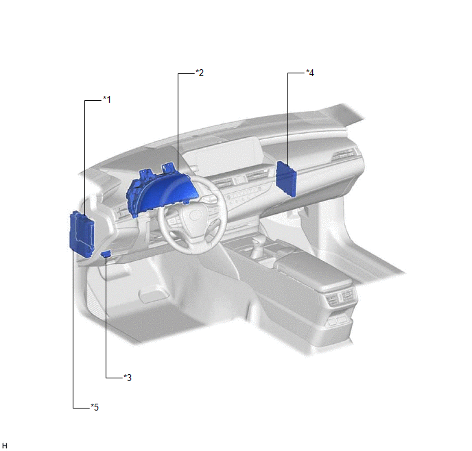
| *1 | MAIN BODY ECU (MULTIPLEX NETWORK BODY ECU) | *2 | COMBINATION METER ASSEMBLY |
| *3 | DLC3 | *4 | CERTIFICATION ECU (SMART KEY ECU ASSEMBLY) |
| *5 | INSTRUMENT PANEL JUNCTION BLOCK ASSEMBLY - ECU-B NO. 2 FUSE - DOOR F/L FUSE - DOOR F/R FUSE - DOOR R/L FUSE - DOOR R/R FUSE | - | - |
ILLUSTRATION
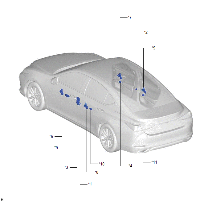
| *1 | FRONT DOOR COURTESY LIGHT SWITCH ASSEMBLY (for LH) | *2 | FRONT DOOR COURTESY LIGHT SWITCH ASSEMBLY (for RH) |
| *3 | FRONT DOOR LOCK WITH MOTOR ASSEMBLY LH | *4 | POWER WINDOW REGULATOR SWITCH ASSEMBLY |
| *5 | MULTIPLEX NETWORK MASTER SWITCH ASSEMBLY | *6 | POWER WINDOW REGULATOR MOTOR ASSEMBLY (for Driver Door) |
| *7 | POWER WINDOW REGULATOR MOTOR ASSEMBLY (for Front Passenger Door) | *8 | POWER WINDOW REGULATOR MOTOR ASSEMBLY (for Rear LH Door) |
| *9 | POWER WINDOW REGULATOR MOTOR ASSEMBLY (for Rear RH Door) | *10 | REAR POWER WINDOW REGULATOR SWITCH ASSEMBLY (for LH Door) |
| *11 | REAR POWER WINDOW REGULATOR SWITCH ASSEMBLY (for RH Door) | - | - |
READ NEXT:
 System Diagram
SYSTEM DIAGRAM Communication Table Transmitting ECU Receiving ECU Signal Communication Method Multiplex Network Master Switch Assembly Power Window Regulator Motor Assembly (for Driv
System Description
SYSTEM DESCRIPTION POWER WINDOW CONTROL SYSTEM DESCRIPTION (a) The power window control system controls the power window operation using the power window regulator motor assemblies. The main controls
How To Proceed With Troubleshooting
CAUTION / NOTICE / HINT HINT:
Use the following procedure to troubleshoot the power window control system.
*: Use the Techstream.
PROCEDURE 1. VEHICLE BROUGHT TO WORKSHOP
NEXT
SEE MORE:
Terminals Of Ecu
TERMINALS OF ECU NOTICE:
DTCs may be output when connectors are disconnected during inspection. Therefore, be sure to clear the DTCs using the Techstream once the inspection has been completed.
Do not apply excessive force to the forward recognition camera connector.
CHECK FORWARD RECOGNITI
Hybrid/EV Battery Precharge Contactor Circuit Short to Ground (P0AE411)
DESCRIPTION The SMRs (System Main Relays) are the relays that connect or disconnect the high-voltage system in accordance with commands from the hybrid vehicle control ECU. There are 3 SMRs and 1 system main resistor. SMRB, SMRP, SMRG and the system main resistor are located in the HV battery juncti
