Lexus ES: Inspection
INSPECTION
PROCEDURE
1. INSPECT CYLINDER HEAD SUB-ASSEMBLY
(a) Using a precision straightedge and feeler gauge, measure the warpage of the contact surfaces where the cylinder head sub-assembly contacts the cylinder block sub-assembly, intake manifold and exhaust manifold (TWC: Front Catalyst).

| *a | Bottom Side | *b | Intake Manifold Side |
| *c | Exhaust Manifold (TWC: Front Catalyst) Side | - | - |
Maximum Warpage:
| Item | Specified Condition |
|---|---|
| Bottom side | 0.05 mm (0.00197 in.) |
| Intake manifold side | 0.10 mm (0.00394 in.) |
| Exhaust manifold (TWC: Front Catalyst) side | 0.10 mm (0.00394 in.) |
HINT:
If the warpage is more than the maximum, replace the cylinder head sub-assembly.
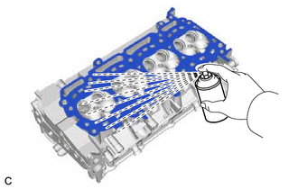
| (b) Using a dye penetrant, check the intake ports, exhaust ports and cylinder head sub-assembly surface for cracks. HINT: If cracks are found, replace the cylinder head sub-assembly. |
|
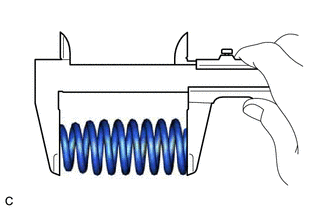
2. INSPECT COMPRESSION SPRING
(a) Intake Side:
| (1) Using a vernier caliper, measure the free length of the compression spring. Standard Free Length: 53.71 mm (2.11 in.) HINT: If the free length is not as specified, replace the compression spring. |
|
| (2) Using a steel square, measure the deviation of the compression spring. Maximum Deviation (Reference): 1.0 mm (0.0394 in.) HINT: If the deviation is more than the maximum, replace the compression spring. |
|

(b) Exhaust Side:
| (1) Using a vernier caliper, measure the free length of the compression spring. Standard Free Length: 55.11 mm (2.17 in.) HINT: If the free length is not as specified, replace the compression spring. |
|
| (2) Using a steel square, measure the deviation of the compression spring. Maximum Deviation (Reference): 1.0 mm (0.0394 in.) HINT: If the deviation is more than the maximum, replace the compression spring. |
|
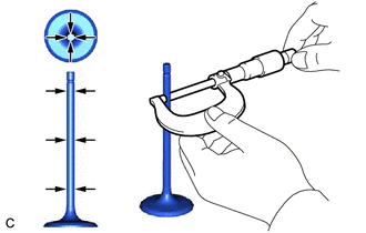
3. INSPECT INTAKE VALVE
| (a) Using a micrometer, measure the diameter of the intake valve stem. Standard Valve Stem Diameter: 5.470 to 5.485 mm (0.215 to 0.216 in.) HINT: If the valve stem diameter is not as specified, check the intake valve guide bush oil clearance. |
|
| (b) Using a vernier caliper, measure the intake valve head margin thickness. Standard Margin Thickness: 1.0 mm (0.0394 in.) Minimum Margin Thickness: 0.5 mm (0.0197 in.) HINT: If the margin thickness is less than the minimum, replace the intake valve. |
|

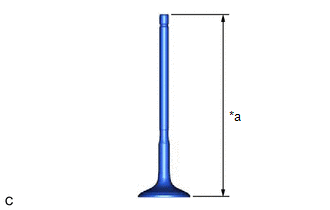
| (c) Using a vernier caliper, measure the overall length of the intake valve. Standard Overall Length: 104.45 mm (4.11 in.) Minimum Overall Length: 103.95 mm (4.09 in.) HINT: If the overall length is less than the minimum, replace the intake valve. |
|

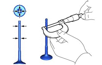
4. INSPECT EXHAUST VALVE
| (a) Using a micrometer, measure the diameter of the exhaust valve stem. Standard Valve Stem Diameter: 5.465 to 5.480 mm (0.215 to 0.216 in.) HINT: If the valve stem diameter is not as specified, check the exhaust valve guide bush oil clearance. |
|
| (b) Using a vernier caliper, measure the exhaust valve head margin thickness. Standard Margin Thickness: 1.0 mm (0.0394 in.) Minimum Margin Thickness: 0.5 mm (0.0197 in.) HINT: If the margin thickness is less than the minimum, replace the exhaust valve. |
|

| (c) Using a vernier caliper, measure the overall length of the exhaust valve. Standard Overall Length: 108.7 mm (4.28 in.) Minimum Overall Length: 108.2 mm (4.26 in.) HINT: If the overall length is less than the minimum, replace the exhaust valve. |
|
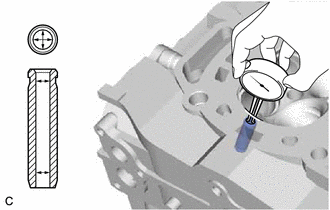
5. INSPECT VALVE GUIDE BUSH OIL CLEARANCE
| (a) Using a caliper gauge, measure the inside diameter of the valve guide bush. Standard Valve Guide Bush Inside Diameter: 5.51 to 5.53 mm (0.217 to 0.218 in.) |
|
(b) Subtract the valve stem diameter measurement from the valve guide bush inside diameter measurement.
Standard Oil Clearance:
| Item | Specified Condition |
|---|---|
| Intake Side | 0.025 to 0.060 mm (0.000984 to 0.00236 in.) |
| Exhaust Side | 0.030 to 0.065 mm (0.00118 to 0.00256 in.) |
Maximum Oil Clearance:
| Item | Specified Condition |
|---|---|
| Intake Side | 0.080 mm (0.00315 in.) |
| Exhaust Side | 0.10 mm (0.00394 in.) |
HINT:
- Oil clearance = Valve guide bush inside diameter - Valve stem diameter
- If the oil clearance is more than the maximum, replace the valve and valve guide bush.
6. INSPECT INTAKE VALVE SEAT
(a) Apply a light coat of Prussian blue to the valve face.
| (b) Lightly press the valve face against the intake valve seat. NOTICE: Do not rotate the valve while pressing it. |
|

(c) Check the valve face and intake valve seat by using the following procedure:
(1) If Prussian blue appears 360° around the entire intake valve face, the valve face is concentric.
HINT:
If the valve face is not concentric, replace the intake valve.
(2) If Prussian blue appears 360° around the entire intake valve seat, the intake valve seat and valve face are concentric.
HINT:
If the valve face is not concentric, replace the cylinder head sub-assembly.
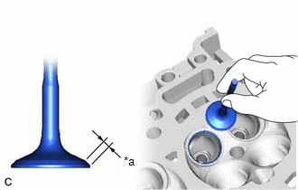
(3) Measure the width of the contact area of the intake valve seat and valve face.
Standard Width:
1.0 to 1.4 mm (0.0394 to 0.0551 in.)
7. INSPECT EXHAUST VALVE SEAT
(a) Apply a light coat of Prussian blue to the valve face.
| (b) Lightly press the valve face against the exhaust valve seat. NOTICE: Do not rotate the valve while pressing it. |
|
(c) Check the valve face and exhaust valve seat by using the following procedure:
(1) If Prussian blue appears 360° around the entire exhaust valve face, the valve face is concentric.
HINT:
If the valve face is not concentric, replace the exhaust valve.
(2) If Prussian blue appears 360° around the entire exhaust valve seat, the exhaust valve seat and valve face are concentric.
HINT:
If the valve face is not concentric, resurface the exhaust valve seat.
(3) Measure the width of the contact area of the exhaust valve seat and valve face.
Standard Width:
1.3 to 1.7 mm (0.0512 to 0.0669 in.)
8. INSPECT CAMSHAFT THRUST CLEARANCE
(a) Clean the No. 1 camshaft bearing cap, No. 2 camshaft bearing cap, 2 No. 3 camshaft bearing caps, No. 4 camshaft bearing cap, camshaft housing sub-assembly and camshaft journals.
(b) Place the camshaft and No. 2 camshaft on the camshaft housing sub-assembly on the cylinder head sub-assembly.
(c) Install the camshaft bearing caps.
Click here .gif)
(d) Install the camshaft housing sub-assembly.
Click here
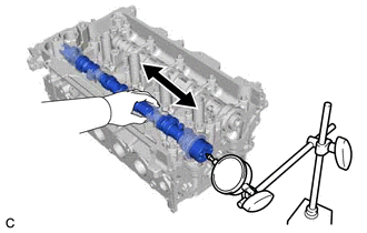
| (e) Using a dial indicator, measure the thrust clearance while moving the camshaft and No. 2 camshaft back and forth. Standard Thrust Clearance:
Maximum Thrust Clearance:
HINT: If the thrust clearance is more than the maximum, replace the camshaft housing sub-assembly. If the thrust surface is damaged, replace the camshaft or No. 2 camshaft. |
|
READ NEXT:
 Replacement
REPLACEMENT PROCEDURE 1. REPLACE INTAKE VALVE GUIDE BUSH (a) Heat the cylinder head sub-assembly to between 80 and 100°C (176 and 212°F). (b) Place the cylinder head sub-assembly on wooden blocks. C
Reassembly
REASSEMBLY PROCEDURE 1. INSTALL SPARK PLUG TUBE HINT: When using a new cylinder head sub-assembly, the spark plug tubes must be replaced. (a) Apply adhesive to a new spark plug tube as shown in the
Repair
REPAIR PROCEDURE 1. REPAIR EXHAUST VALVE SEAT NOTICE:
While repairing the exhaust valve seat, make sure to constantly check the valve seat width and valve seating position.
Release the cutter gra
SEE MORE:
Automatic High Beam System does not Operate or Operation Indicator does not Illuminate
DESCRIPTION The main body ECU (multiplex network body ECU) controls the automatic high beam system based on signals received from the forward recognition camera. WIRING DIAGRAM CAUTION / NOTICE / HINT NOTICE:
Before replacing the main body ECU (multiplex network body ECU), refer to Registration.
Cleaning the hybrid battery (traction
battery) air intake vent and
filter
To prevent the fuel economy from
being affected, visually inspect the
hybrid battery (traction battery) air
intake vent periodically for dust and
clogs. If it is dusty or clogged or if
"Maintenance Required for Traction
Battery Cooling Parts See
Owner's Manual" is displayed on
the multi-info
