Lexus ES: Panel Switches do not Function
Lexus ES (XZ10) Service Manual / Audio & Visual & Telematics / Audio / Video / Audio And Visual System (for Gasoline Model) / Panel Switches do not Function
CAUTION / NOTICE / HINT
NOTICE:
-
Depending on the parts that are replaced during vehicle inspection or maintenance, performing initialization, registration or calibration may be needed. Refer to Precaution for Audio and Visual System.
Click here
.gif)
-
When replacing the radio receiver assembly, always replace it with a new one. If a radio receiver assembly which was installed to another vehicle is used, the following may occur:
- A communication malfunction DTC may be stored.
- The radio receiver assembly may not operate normally.
PROCEDURE
| 1. | CHECK PANEL SWITCH |
(a) Check for foreign matter around the switches that might prevent operation.
OK:
No foreign matter is found.
| NG | .gif) | REMOVE ANY FOREIGN MATTER FOUND |
|
.gif)
| 2. | CHECK PANEL & STEERING SWITCH (OPERATION CHECK) |
| (a) Enter the "Panel & Steering Switch Check Mode" screen. Refer to Check Panel & Steering Switch in Operation Check. Click here |
|
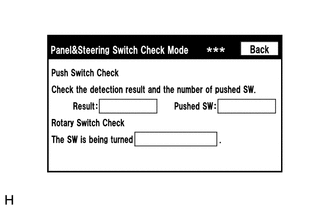
(b) Operate the abnormal switch and check if the switch status is correctly displayed.
OK:
The switch status is correctly displayed as operated.
| OK | | REPLACE RADIO RECEIVER ASSEMBLY |
| NG | | PROCEED TO NEXT SUSPECTED AREA SHOWN IN PROBLEM SYMPTOMS TABLE |
READ NEXT:
 Parts Location
PARTS LOCATION ILLUSTRATION *1 TELEPHONE MICROPHONE ASSEMBLY *2 INSTRUMENT PANEL JUNCTION BLOCK ASSEMBLY - ECU-ACC FUSE - ECU-IG1 NO. 4 FUSE - PANEL FUSE - METER-IG2 FUSE - ECU-IG2 NO. 3 FUS
Pointer Displayed/not Displayed Repeatedly
WIRING DIAGRAM CAUTION / NOTICE / HINT NOTICE:
Depending on the parts that are replaced during vehicle inspection or maintenance, performing initialization, registration or calibration may be need
Pointer not Displayed on Screen or Pointer does not Move
CAUTION / NOTICE / HINT NOTICE:
Depending on the parts that are replaced during vehicle inspection or maintenance, performing initialization, registration or calibration may be needed. Refer to Pre
SEE MORE:
Hybrid/EV Powertrain Control Module Monitoring Processor Unexpected Operation (P060A94)
DTC SUMMARY MALFUNCTION DESCRIPTION The main CPU and sub CPU of the hybrid vehicle control ECU monitor their internal operation and each other for malfunctions. The cause of this malfunction may be the following: Hybrid vehicle control ECU internal malfunction
Hybrid vehicle control ECU malfuncti
Inspection
INSPECTION PROCEDURE 1. INSPECT BRAKE VACUUM CHECK VALVE ASSEMBLY (a) Check that there is ventilation from the booster side to the engine side, and no ventilation from the engine side to the booster side of the brake vacuum check valve assembly. HINT: If the result is not as specified, replace th
© 2016-2026 Copyright www.lexguide.net
