Lexus ES: Turn Signal Switch Circuit
DESCRIPTION
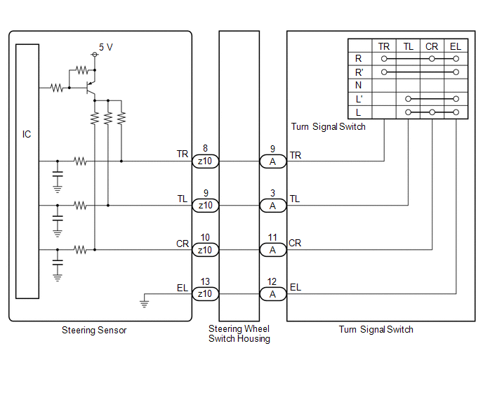
The steering sensor receives the turn signal switch information and controls the turn signal lights.
WIRING DIAGRAM
PROCEDURE
| 1. | READ VALUE USING TECHSTREAM |
(a) Connect the Techstream to the DLC3.
(b) Turn the engine switch on (IG).
(c) Turn the Techstream on.
(d) Enter the following menus: Chassis / Steering Angle Sensor / Data List.
(e) Read the Data List according to the display on the Techstream.
Chassis > Steering Angle Sensor > Data List| Tester Display | Measurement Item | Range | Normal Condition | Diagnostic Note |
|---|---|---|---|---|
| Turn Signal Switch (Right) | Turn signal switch (right turn position) signal | OFF or ON | OFF: Turn signal switch not in right turn position ON: Turn signal switch in right turn position | - |
| Turn Signal Switch (Left) | Turn signal switch (left turn position) signal | OFF or ON | OFF: Turn signal switch not in left turn position ON: Turn signal switch in left turn position | - |
| Cornering Light/Front Side Illuminate Light Switch | Turn signal switch (full turn) signal | OFF or ON | OFF: Turn signal switch not in left or right turn position ON: Turn signal switch in left or right full turn position | - |
| Tester Display |
|---|
| Turn Signal Switch (Right) |
| Turn Signal Switch (Left) |
| Cornering Light/Front Side Illuminate Light Switch |
OK:
Normal conditions listed above are displayed.
| OK | .gif) | PROCEED TO NEXT SUSPECTED AREA SHOWN IN PROBLEM SYMPTOMS TABLE |
|
.gif)
| 2. | INSPECT TURN SIGNAL SWITCH |
(a) Remove the turn signal switch.
Click here .gif)
(b) Inspect the turn signal switch.
Click here
| NG | | REPLACE TURN SIGNAL SWITCH |
|
| 3. | INSPECT STEERING WHEEL SWITCH HOUSING |
(a) Remove the steering wheel switch housing.
Click here
(b) Inspect the steering wheel switch housing.
Click here
| OK | | REPLACE STEERING SENSOR |
| NG | | REPLACE STEERING WHEEL SWITCH HOUSING |
READ NEXT:
 Automatic High Beam Switch Indicator does not Come ON
DESCRIPTION When the automatic high beam system is on, the steering sensor illuminates the automatic high beam switch indicator. WIRING DIAGRAM PROCEDURE 1. READ VALUE USING TECHSTREAM (a) C
Automatic High Beam System does not Operate or Operation Indicator does not Illuminate
DESCRIPTION The main body ECU (multiplex network body ECU) controls the automatic high beam system based on signals received from the forward recognition camera. WIRING DIAGRAM CAUTION / NOTICE / HIN
Headlight Dimmer Switch Circuit
DESCRIPTION The steering sensor receives the following switch information:
Light control switch in DRL OFF*1, off*2, tail, head or AUTO position
Dimmer switch in high, low or high flash (pass) po
SEE MORE:
Customize Parameters
CUSTOMIZE PARAMETERS CUSTOMIZE POWER WINDOW CONTROL SYSTEM HINT: The following items can be customized. NOTICE:
When the customer requests a change in a function, first make sure that the function can be customized.
Be sure to make a note of the current settings before customizing.
When troub
Precaution
PRECAUTION PRECAUTION FOR DISCONNECTING CABLE FROM NEGATIVE BATTERY TERMINAL NOTICE: When disconnecting the cable from the negative (-) battery terminal, initialize the following system(s) after the cable is reconnected: System See Procedure Lane Control System (for Gasoline Model)
