Lexus ES: Transmission Fluid Temperature Sensor "A" Circuit Range/Performance (P071000)
DESCRIPTION
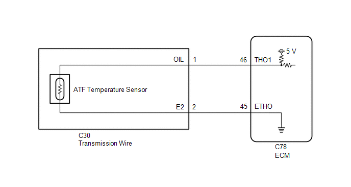
The ATF temperature sensor converts the automatic transaxle fluid (ATF) temperature into a resistance value for use by the ECM.
The ECM applies a voltage to the temperature sensor through terminal THO1 of the ECM.
The sensor resistance changes with the ATF temperature. As the temperature rises, the sensor resistance decreases.
One terminal of the sensor is grounded so that the sensor resistance and voltage decrease as the temperature rises.
The ECM calculates the ATF temperature based on the voltage signal.
| DTC No. | Detection Item | DTC Detection Condition | Trouble Area | MIL | Memory | Note |
|---|---|---|---|---|---|---|
| P071000 | Transmission Fluid Temperature Sensor "A" Circuit Range/Performance | Either of the following condition is met (2-trip detection logic):
|
| Comes on | DTC stored | SAE Code: P0711 |
| Vehicle Condition | |||
|---|---|---|---|
| Pattern 1 | Pattern 2 | ||
| Diagnostic Condition | Certain monitor enabling conditions are met. | ○ | ○ |
| Malfunction Condition | The ATF temperature is below 20°C (68°F). | ○ | - |
| The ATF temperature is 100°C (212°F) or higher. | - | ○ | |
| Duration | 3 seconds or more | 3 seconds or more | |
| Detection Logic | 2-trip detection logic | 2-trip detection logic | |
HINT:
This DTC is stored when either of the above detection patterns is met.
MONITOR DESCRIPTION
This DTC indicates that there is a problem with the output signals from the ATF temperature sensor and that the sensor itself is defective. The ATF temperature sensor converts the ATF temperature into an electrical resistance value. Based on the resistance, the ECM determines the ATF temperature and detects an open or short in the ATF temperature circuit or a malfunction of the ATF temperature sensor.
After driving the vehicle for a certain period of time, the ATF temperature should increase. If the ATF temperature is below 20°C (68°F) after driving the vehicle for a certain period, the ECM interprets this as a malfunction, illuminates the MIL and stores this DTC.
If the ATF temperature is 100°C (212°F) or higher and the engine coolant temperature takes 10 seconds or more to reach 60°C (140°F) after a cold start, the ECM also interprets this as a malfunction, illuminates the MIL and stores this DTC.
MONITOR STRATEGY
| Related DTCs | P0711: ATF temperature sensor/Rationality fault diagnostics |
| Required sensors/components | ATF temperature sensor (TFT sensor) |
| Frequency of operation | Continuous |
| Duration | 3 sec. |
| MIL operation | 2 driving cycles |
| Sequence of operation | None |
TYPICAL ENABLING CONDITIONS
ALL:| The monitor will run whenever the following DTCs are not stored | P0112, P0113 (IAT (Intake air temperature) sensor circuit) P0717, P07BF, P07C0 (Turbine speed sensor circuit) P0793, P07C5, P07C6 (Intermediate shaft speed sensor circuit) P0962, P0963 (Solenoid (SL1) valve circuit) P0966, P0967 (Solenoid (SL2) valve circuit) P0970, P0971 (Solenoid (SL3) valve circuit) P2814, P2815 (Solenoid (SL4) valve circuit) P281D, P281E (Solenoid (SL5) valve circuit) P08C1, P08C2 (Solenoid (SL6) valve circuit) P0743 (Solenoid (SL) valve circuit) P2759 (Solenoid (SLU) valve circuit) P0117, P0118 (ECT (Engine coolant temperature) sensor circuit) P0712, P0713 (ATF temperature sensor circuit (TFT sensor)) P0327, P0328, P0332, P0333 (KCS sensor circuit) P0121, P0122, P0123, P0222, P0223, P0604, P0606, P060A, P060B, P060D, P060E, P061E, P0657, P0658, P2102, P2103, P2111, P2112, P2119, P2135 ((ETCS) Electronic throttle control system) U0100 (CAN communication system) P0335 (Crankshaft position sensor "A" circuit) P2610 (Soak timer circuit) |
| Time after engine start except for continuing shift position "N" or "P"*2 | 10 min. or more |
| Accumulated driving time *1 | 3 min. and 30 sec. or more |
| Driving distance after engine start*3 | 5 km (3.1 miles) or more |
| IAT*4 | 15°C (59°F) or higher |
| ECT (12 sec. after engine start) Duration | 15°C (59°F) or higher |
| Soak time | 5 hours or more |
| Time after engine start except for continuing shift position "N" or "P"*2 | 18 min. and 20 sec. or more |
| Accumulated driving time*1 | 5 min. and 55 sec. or more |
| Driving distance after engine start*3 | 8 km (5 mile) or more |
| IAT*4 | -10°C (14°F) or more |
| ECT (12 sec. after engine start) | -10°C (14°F) or more |
| Time after engine start except for continuing shift position "N" or "P"*2 | 30 min. or more |
| Accumulated driving time*1 | 9 min. and 40 sec. or more |
| Driving distance after engine start*3 | 15 km (9.3 mile) |
| IAT*4 | -15°C (5°F) or more |
| ECT (12 sec. after engine start) | -15°C (5°F) or more |
| Time after engine start except for continuing shift position "N" or "P"*2 | 40 min. or more |
| Accumulated driving time*1 | 12 min. and 50 sec. or more |
| Driving distance after engine start*3 | 20 km (12.4 mile) |
| Any of the following conditions is met | - |
| - Elapsed time for ECT to reach 60°C (140°F) | 10 sec. or more |
| - Soak time | 5 hours or more |
| ATF temperature (12 sec. after engine start) | 100°C (212°F) or higher |
| ECT (12 sec. after engine start) | Below 35°C (95°F) |
HINT:
*1: Following conditions are met
| Engine speed - Turbine speed | -50 rpm or more |
| Output speed | 400 rpm or more |
| Throttle valve opening angle | 3% or more |
| Shift position | Not "N" or "P" |
| Engine | Starting |
| Accumulated driving time is cleared when following condition met | - |
| Duration time from shift position "N" or "P" | 300 sec. or more |
*2: Time after engine start is cleared when following condition met
| Duration time from shift position "N" or "P" | 300 sec. or more |
*3: Driving distance is cleared when following condition met
| Duration time from shift position "N" or "P" | 300 sec. or more |
*4: IAT is measured when either of following conditions met
| 12 sec. after engine start | - |
| Duration time from shift position "N" or "P" | 300 sec. or more |
TYPICAL MALFUNCTION THRESHOLDS
One of the following conditions is met: Condition (A), (B), (C), (D) or (E)
Condition (A), (B), (C) and (D)| Duration time from engine start | 12 sec. or more |
| ECT | -15°C (5°F) or higher |
| ATF temperature | Below 20°C (68°F) |
| ATF temperature | 100°C (212°F) or higher |
COMPONENT OPERATING RANGE
| ATF temperature | 20°C (68°F) or higher and below 100°C (212°F) |
CONFIRMATION DRIVING PATTERN
CAUTION:
When performing the confirmation driving pattern, obey all speed limits and traffic laws.
HINT:
- After repairs have been completed, clear the DTCs and then check that the vehicle has returned to normal by performing the following All Readiness check procedure.
-
When clearing the permanent DTCs, refer to the Clear Permanent DTC procedure.
Click here
.gif)
- Connect the Techstream to the DLC3.
- Turn the engine switch on (IG) and turn the Techstream on.
- Clear the DTCs (even if no DTCs are stored, perform the clear DTC procedure).
- Turn the engine switch off and wait for at least 5 hours. [*1]
- Turn the engine switch on (IG) and turn the Techstream on. [*2]
-
Start the engine and perform both of the following [*3]:
- Drive the vehicle 20 km (12 mile) or more over a period of 12 minutes and 50 seconds or more.
-
Wait until 40 minutes or more have elapsed since the engine started.
HINT:
[*1] to [*3] : Normal judgment procedure.
The normal judgment procedure is used to complete DTC judgment and also used when clearing permanent DTCs.
- Stop the vehicle.
- Enter the following menus: Powertrain / Transmission / Utility / All Readiness.
- Input the DTC: P071000.
-
Check the DTC judgment result.
Techstream Display
Description
NORMAL
- DTC judgment completed
- System normal
ABNORMAL
- DTC judgment completed
- System abnormal
INCOMPLETE
- DTC judgment not completed
- Perform driving pattern after confirming DTC enabling conditions
N/A
- Unable to perform DTC judgment
- Number of DTCs which do not fulfill DTC preconditions has reached ECU memory limit
HINT:
- If the judgment result shows NORMAL, the system is normal.
- If the judgment result shows ABNORMAL, the system has a malfunction.
- If the judgment result shows INCOMPLETE or N/A, perform the normal judgment procedure again.
WIRING DIAGRAM
CAUTION / NOTICE / HINT
NOTICE:
-
Perform the universal trip to clear permanent DTCs.
Click here
-
Perform registration and/or initialization when parts related to the automatic transaxle are replaced.
Click here
-
If DTCs P071000, P261029 and/or P261093 are output simultaneously, using the Techstream, check if the ATF temperature is as specified under the "Normal Condition" column of the Data List. If the ATF temperature is as specified under the "Normal Condition" column, perform troubleshooting for DTC P261029.
Click here
DATA LIST
NOTICE:
In the table below, the values listed under "Normal Condition" are reference values. Do not depend solely on these reference values when deciding whether a part is faulty or not.
HINT:
Using the Techstream to read the Data List allows the values or states of switches, sensors, actuators and other items to be read without removing any parts. This non-intrusive inspection can be very useful because intermittent conditions or signals may be discovered before parts or wiring is disturbed. Reading the Data List information early in troubleshooting is one way to save diagnostic time.
(a) Warm up the engine.
(b) Turn the engine switch off.
(c) Connect the Techstream to the DLC3.
(d) Turn the engine switch on (IG).
(e) Turn the Techstream on.
(f) Enter the following menus: Powertrain / Transmission / Data List / A/T Oil Temperature No.1.
(g) Read the Data List according to the display on the Techstream.
Powertrain > Transmission > Data List| Tester Display | Measurement Item | Range | Normal Condition | Diagnostic Note |
|---|---|---|---|---|
| A/T Oil Temperature No.1 | ATF temperature sensor value | Min.: -40°C (-40°F) Max.: 150°C (302°F) |
| If value is -40°C (-40°F) or 150°C (302°F), ATF temperature sensor circuit is open or shorted |
| Tester Display |
|---|
| A/T Oil Temperature No.1 |
HINT:
- If DTC P071011 is output and the Techstream indicates 150°C (302°F) or higher, there is a short in the circuit.
-
If DTC P071015 is output and the Techstream indicates -40°C (-40°F), the circuit is open.
Check the temperature displayed on the Techstream in order to check if a malfunction exists.
Temperature Displayed
Malfunction
-40°C (-40°F)
Open circuit
150°C (302°F) or higher
Short circuit
- If a circuit related to the ATF temperature sensor becomes open, P071015 will be stored in approximately 0.5 seconds. If DTC P071015 is stored, DTC P071000 cannot be detected. It is not necessary to inspect the circuit when P071000 is output.
PROCEDURE
| 1. | CHECK OTHER DTCS OUTPUT (IN ADDITION TO DTC P071000) |
(a) Connect the Techstream to the DLC3.
(b) Turn the engine switch on (IG).
(c) Turn the Techstream on.
(d) Enter the following menus: Powertrain / Transmission / Trouble Codes.
Powertrain > Transmission > Trouble Codes(e) Read the DTCs using the Techstream.
| Result | Proceed to |
|---|---|
| Only DTC P071000 is output | A |
| DTC P071000 and P071015 are output | B |
| DTC P071000 and other DTCs are output | C |
HINT:
If any DTCs other than DTC P071000 are output, perform troubleshooting for those DTCs first.
| B | .gif) | GO TO DTC CHART (DTC P071015) |
| C | | GO TO DTC CHART |
|
.gif)
| 2. | INSPECT AUTOMATIC TRANSAXLE FLUID LEVEL |
(a) Check the automatic transaxle fluid level.
Click here
OK:
Automatic transaxle fluid level is correct.
| NG | | ADJUST AUTOMATIC TRANSAXLE FLUID LEVEL |
|
| 3. | CHECK TRANSMISSION WIRE CIRCUIT |
(a) Disconnect the C78 ECM connector.
(b) Measure the resistance according to the value(s) in the table below.
Standard Resistance:
| Tester Connection | Condition | Specified Condition |
|---|---|---|
| C78-46 (THO1) - C78-45 (ETHO) | ATF temperature 10°C (50°F) | 5 to 8 kΩ |
| C78-46 (THO1) - C78-45 (ETHO) | ATF temperature 110°C (230°F) | 0.22 to 0.28 kΩ |
| C78-45 (ETHO) - Body ground | Always | 10 kΩ or higher |
| C78-46 (THO1) - Body ground | Always | 10 kΩ or higher |
HINT:
If the resistance is out of the specified range at the ATF temperature shown in the table below, the driveability of the vehicle may decrease.
| ATF Temperature | Specified Condition |
|---|---|
| 25°C (77°F) | 2.5 to 4.5 kΩ |
| NG | | GO TO STEP 5 |
|
| 4. | REPLACE ECM |
(a) Replace the ECM.
Click here
| NEXT | | PERFORM REGISTRATION |
| 5. | CHECK HARNESS AND CONNECTOR (TRANSMISSION WIRE - ECM) |
(a) Disconnect the C30 transmission wire connector.
(b) Disconnect the C78 ECM connector.
(c) Measure the resistance according to the value(s) in the table below.
Standard Resistance:
| Tester Connection | Condition | Specified Condition |
|---|---|---|
| C30-1 (OIL) - C78-46 (THO1) | Always | Below 1 Ω |
| C30-2 (E2) - C78-45 (ETHO) | Always | Below 1 Ω |
| C30-1 (OIL) or C78-46 (THO1) - Body ground | Always | 10 kΩ or higher |
| C30-2 (E2) or C78-45 (ETHO) - Body ground | Always | 10 kΩ or higher |
| OK | | REPLACE TRANSMISSION WIRE (ATF TEMPERATURE SENSOR) |
| NG | | REPAIR OR REPLACE HARNESS OR CONNECTOR (TRANSMISSION WIRE - ECM) |
READ NEXT:
 Transmission Fluid Temperature Sensor "A" Circuit Short To Ground (P071011)
DESCRIPTION The ATF temperature sensor converts the automatic transaxle fluid (ATF) temperature into a resistance value for use by the ECM. The ECM applies voltage to the temperature sensor through te
Transmission Fluid Temperature Sensor "A" Circuit Short to Battery or Open (P071015)
DESCRIPTION The ATF temperature sensor converts the automatic transaxle fluid (ATF) temperature into a resistance value for use by the ECM. The ECM applies voltage to the temperature sensor through te
Input/Turbine Speed Sensor "A" Circuit Short to Battery (P071512,P071514,P071531)
DESCRIPTION The transmission revolution sensor (NT) detects the input shaft rotation speed and sends it to the ECM. Based on the transmission revolution sensor (NT) signal and the transmission revolut
SEE MORE:
Installation
INSTALLATION PROCEDURE 1. INSTALL EGR COOLER ASSEMBLY (a) Install a new EGR cooler gasket to the EGR cooler assembly. NOTICE: Make sure that the claws of the EGR cooler gasket are toward the EGR cooler assembly side. *a Claw (b) Install a new EGR valve gasket to the EGR
Removal
REMOVAL CAUTION / NOTICE / HINT The necessary procedures (adjustment, calibration, initialization, or registration) that must be performed after parts are removed and installed, or replaced during rear shock absorber assembly removal/installation are shown below. Necessary Procedures After Parts Rem
