Lexus ES: Torque Converter And Drive Plate
Inspection
INSPECTION
PROCEDURE
1. INSPECT TORQUE CONVERTER ASSEMBLY
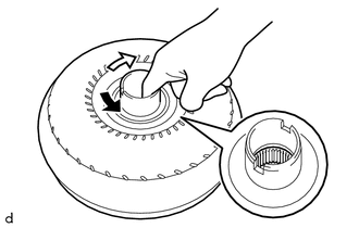
(a) Inspect the one-way clutch. Press on the splines of the stator with a finger and rotate it. Check that it rotates smoothly when turned clockwise and rotates with difficulty when turned counterclockwise.
.png) | Difficult |
.png) | Smooth |
If necessary, clean the torque converter assembly and recheck the one-way clutch. Replace the torque converter assembly if the one-way clutch still fails the inspection.
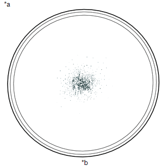
| (b) Inspect the torque converter assembly. If any of the following problems are present, replace the torque converter assembly. Malfunction:
HINT: The sample shows approximately 0.025 liters (0.026 US qts, 0.022 Imp. qts) of ATF in a Petri dish, which has been taken from the removed torque converter assembly. |
|
(c) Replace the ATF in the torque converter assembly.
HINT:
If the ATF is discolored or has a foul odor, stir the ATF in the torque converter assembly and drain it before replacing the ATF.
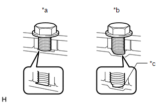
| (d) Prevent deformation of the torque converter assembly and damage to the oil pump gear. NOTICE: Make sure that all of the bolts are the same length and that the specified bolts are used. HINT: If there is any damage to the tip of a bolt for the torque converter assembly or to the bottom of a bolt hole, replace the bolt and torque converter assembly. |
|
2. INSPECT DRIVE PLATE AND RING GEAR SUB-ASSEMBLY
(a) Check the drive plate and ring gear sub-assembly for damage.
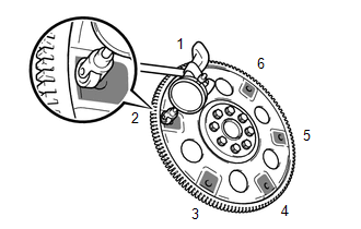
.png) | Measurement Point |
(b) Set up a dial indicator and measure the runout at the 6 areas on the drive plate and ring gear sub-assembly surface that contact the torque converter clutch assembly.
Maximum Runout:
0.30 mm (0.0118 in.)
HINT:
- If the runout is more than the maximum or the drive plate and ring gear sub-assembly is damaged, replace the drive plate and ring gear sub-assembly.
-
If installing a new drive plate and ring gear sub-assembly, confirm that the spacers are oriented properly before tightening the bolts.
Click here
.gif)
READ NEXT:
 Adjustment
ADJUSTMENT PROCEDURE 1. SECURE VEHICLE (a) Fully apply the parking brake and chock a wheel. CAUTION:
Make sure to apply the parking brake and chock a wheel before performing this procedure.
If th
Components
COMPONENTS ILLUSTRATION *1 BATTERY CLAMP SUB-ASSEMBLY - - N*m (kgf*cm, ft.*lbf): Specified torque - - ILLUSTRATION *1 FRONT LOWER NO. 1 FLOOR HEAT INSULATOR - -
SEE MORE:
Installation
INSTALLATION PROCEDURE 1. INSTALL FLOW SHUTTING VALVE (WATER BY-PASS HOSE ASSEMBLY) (a) Connect the flow shutting valve (water by-pass hose assembly) to the water by-pass outlet sub-assembly and slide the clip to secure it. NOTICE:
Make sure to slide the flow shutting valve (water by-pass ho
Right Headlight ECU Malfunction (B242C,B242D)
DESCRIPTION The headlight ECU sub-assembly LH or headlight ECU sub-assembly RH stores a DTC if it detects an internal malfunction. for LED Type Turn Signal Light DTC No. Detection Item DTC Detection Condition Trouble Area DTC Output from B242C Right Headlight ECU Malfunction
Th
