Lexus ES: Test Mode Procedure
TEST MODE PROCEDURE
TEST MODE (SIGNAL CHECK MODE) PROCEDURE
HINT:
-
When entering test mode (signal check mode), the tire pressure warning ECU and receiver sets all the test mode (signal check mode) DTCs first.
After the tire pressure warning ECU and receiver completes the signal check for each inspection item, the DTCs for systems that are determined to be normal will be cleared.
The DTCs for other inspection items may not be cleared when only a certain signal is inspected.
- When test mode (signal check mode) returns to normal mode, all the test mode (signal check mode) DTCs will be cleared.
- Operation of the tire pressure warning reset switch can be checked in test mode (signal check mode).
- During test mode (signal check mode), the system will not be initialized by operating the steering pad switch assembly. The circuit of the tire pressure warning reset switch can be inspected during this mode.
(a) Turn the power switch off.
(b) Connect the Techstream to the DLC3.
(c) Turn the power switch on (IG).
(d) Turn the Techstream on.
(e) Enter the following menus: Chassis / Tire Pressure Monitor / Utility / Signal Check.
Chassis > Tire Pressure Monitor > Utility| Tester Display |
|---|
| Signal Check |
HINT:
Every time the test mode (signal check mode) DTC clear conditions are satisfied, the tire pressure warning light illuminates for 1 second. Following this, the tire pressure warning light blinks at 0.125 second intervals.
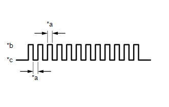
| *a | 0.125 sec. |
| *b | ON |
| *c | OFF |
(f) Tire pressure warning reset switch check (DTC C2198).
(1) Select "Set Pressure" on the multi-information display and press the "OK" switch (steering pad switch assembly).
(g) Transmitter data reception check (DTCs C2181 to C2184).
(1) Wait for 1.5 minutes with the vehicle stopped, or drive the vehicle at a speed of 50 km/h (31 mph) or more for 1 minute.
HINT:
The tire pressure warning valve and transmitters send signals to the tire pressure warning ECU and receiver once every 1.5 minutes while the vehicle is stopped and once every minute while driving.
(h) Check that the tire pressure warning system test mode (signal check mode) DTCs are cleared.
| Test Mode (Signal Check Mode) DTC | Test Signal | Test Mode (Signal Check Mode) DTC Clear Condition |
|---|---|---|
| C2181 to C2184 | Transmitter Data | Data is received from the relevant transmitter which has a registered ID in the tire pressure warning ECU and receiver. |
| C2198 | Tire Pressure Warning Reset Switch Signal | A signal is received indicating that the steering pad switch assembly is operated, "Set Pressure" on the multi-information display is selected and the "OK" switch (steering pad switch assembly) is pressed. |
(i) Result
HINT:
After the signal check is completed, check for test mode (signal check mode) DTCs to confirm the system status.
| Condition | Procedure |
|---|---|
| Test mode (signal check mode) DTCs are output | Repair the faulty part and enter Signal Check again |
| Test mode (signal check mode) DTCs are cleared | No problem |
(j) End of test mode (signal check mode)
(1) After completing test mode (signal check mode), turn the power switch off and disconnect the Techstream.
(k) Test mode (signal check mode) DTCs
(1) If a trouble code is displayed during the test mode (signal check mode) DTC check, check the diagnosis procedure listed for that code. For details of each code, refer to Link below.
| DTC No. | Detection Item | Trouble Area | Link |
|---|---|---|---|
| C2181 | Transmitter ID1 not received |
| |
| C2182 | Transmitter ID2 not received |
| |
| C2183 | Transmitter ID3 not received |
| |
| C2184 | Transmitter ID4 not received |
| |
| C2198 | Initialization switch error |
| |
.gif)
READ NEXT:
 Problem Symptoms Table
PROBLEM SYMPTOMS TABLE HINT:
Use the table below to help determine the cause of problem symptoms. If multiple suspected areas are listed, the potential causes of the symptoms are listed in order of
Terminals Of Ecu
TERMINALS OF ECU CHECK TIRE PRESSURE WARNING ECU AND RECEIVER (a) Disconnect the N8 tire pressure warning ECU and receiver connector and measure the voltage or resistance on the wire harness side.
Diagnosis System
DIAGNOSIS SYSTEM CHECK WARNING LIGHT NOTICE:
When there is a problem with the tire pressure warning system, the tire pressure warning light blinks at 0.5 second intervals, and illuminates after 1 m
SEE MORE:
Fuel Level Sensor "A" Circuit Short to Battery (P046012,P046014)
DESCRIPTION The fuel sender gauge is located inside the fuel tank and measures the amount of fuel. The fuel sender gauge converts the fuel level in the fuel tank into a voltage value and outputs it to the combination meter assembly. The ECM determines when it is necessary to refuel the vehicle based
Removal
REMOVAL CAUTION / NOTICE / HINT HINT:
Use the same procedure for the RH side and LH side.
The following procedure is for the LH side.
PROCEDURE 1. PRECAUTION Click here 2. RELEASE PARKING BRAKE (a) Move the shift lever to P. (b) Turn the engine switch (for Gasoline Model) or power switch (
