Lexus ES: Removal
REMOVAL
CAUTION / NOTICE / HINT
HINT:
- Use the same procedure for the RH side and LH side.
- The following procedure is for the LH side.
PROCEDURE
1. PRECAUTION
Click here .gif)
2. RELEASE PARKING BRAKE
(a) Move the shift lever to P.
(b) Turn the engine switch (for Gasoline Model) or power switch (for HV Model) on (IG).
(c) Operate the electric parking brake switch assembly to release the parking brake.
HINT:
If the parking brake cannot be released:
for HV Model: Click here
for Gasoline Model: Click here
(d) Turn the engine switch (for Gasoline Model) or power switch (for HV Model) off.
3. REMOVE REAR WHEEL
Click here
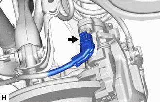
4. DISCONNECT NO. 2 PARKING BRAKE WIRE ASSEMBLY
| (a) Disconnect the No. 2 parking brake wire assembly connector from the parking brake actuator assembly. NOTICE:
|
|
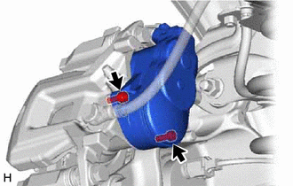
5. REMOVE PARKING BRAKE ACTUATOR ASSEMBLY
| (a) Using a 5 mm hexagon socket wrench, remove the 2 bolts and parking brake actuator assembly from the rear disc brake cylinder assembly. NOTICE:
|
|
(b) Remove the O-ring from the rear disc brake cylinder assembly.
READ NEXT:
 Electric Parking Brake Switch
ComponentsCOMPONENTS ILLUSTRATION *1 ELECTRIC PARKING BRAKE SWITCH ASSEMBLY *2 LOWER INSTRUMENT PANEL *3 INSTRUMENT PANEL FINISH PANEL END - - InspectionINSPECTION PROCEDURE 1
Brake Warning Light (Yellow) Remains On
DESCRIPTION This procedure is for troubleshooting when the brake warning light (yellow) remains on but no DTCs are output. The skid control ECU (brake actuator assembly) controls the brake warning lig
SEE MORE:
Inspection
INSPECTION PROCEDURE 1. INSPECT THROTTLE BODY WITH MOTOR ASSEMBLY (a) Measure the resistance according to the value(s) in the table below. Standard Resistance: Tester Connection Condition Specified Condition 5 (M-) - 6 (M+) 20°C (68°F) 0.3 to 100 Ω If the result is not as sp
Speaker Output Short (B15C3)
DESCRIPTION This DTC is stored when a malfunction occurs in the speakers. DTC No. Detection Item DTC Detection Condition Trouble Area B15C3 Speaker Output Short A short is detected in the speaker output circuit.
Harness or connector
Speaker
Stereo component amplifier assemb
