Lexus ES: Terminals Of Ecu
TERMINALS OF ECU
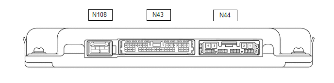
PARKING ASSIST ECU
(a) Disconnect the N44 parking assist ECU connector.
(b) Measure the voltage and resistance according to the value(s) in the table below.
| Terminal No. (Symbol) | Wiring Color | Terminal Description | Condition | Specified Condition |
|---|---|---|---|---|
| N44-1 (+B) - N44-4 (GND1) | R - W-B | Power source signal | Always | 11 to 14 V |
| N44-4 (GND1) - Body ground | W-B - Body ground | Ground | Always | Below 1 Ω |
| N44-3 (IG) - N44-4 (GND1) | BE - W-B | IG power source signal | Engine switch on (IG) | 11 to 14 V |
| Engine switch off | Below 1 V | |||
| N44-2 (ACC) - N44-4 (GND1) | L - W-B | ACC power source signal | Engine switch on (ACC) | 11 to 14 V |
| Engine switch off | Below 1 V |
(c) Reconnect the N44 parking assist ECU connector.
(d) Measure the voltage, resistance and waveform according to the value(s) in the table below.
| Terminal No. (Symbol) | Wiring Color | Terminal Description | Condition | Specified Condition |
|---|---|---|---|---|
| N43-29 (CV+) - N43-32 (CGND) | B - R | Rear television camera assembly display signal input | Engine switch on (IG) with the camera lens of the rear television camera assembly not covered, displaying the panoramic image | Pulse generation (See waveform 1) |
| Engine switch on (IG) with the camera lens of the rear television camera assembly covered, blacking out the panoramic image | Pulse generation (See waveform 2) | |||
| N43-30 (CV-) - N44-4 (GND1) | W - W-B | Rear television camera assembly ground | Always | Below 1 Ω |
| N43-38 (RCV+) - N43-17 (RGND) | W - G | Side television camera assembly RH display signal input | Engine switch on (IG) with the camera lens of the side television camera assembly RH not covered, displaying the panoramic image | Pulse generation (See waveform 1) |
| Engine switch on (IG) with the camera lens of the side television camera assembly RH covered, blacking out the panoramic image | Pulse generation (See waveform 2) | |||
| N43-16 (RCV-) - N44-4 (GND1) | R - W-B | Side television camera assembly RH ground | Always | Below 1 Ω |
| N43-40 (RCB+) - N43-17 (RGND) | B - G | Power source to side television camera assembly RH | Engine switch on (IG) | 5.5 to 7.05 V |
| N43-6 (RSW+) - N44-4 (GND1) | B - W-B | Terminal required by law | Panoramic image being displayed | 0 to 2 V |
| Panoramic image not being displayed | 5.5 to 7.05 V | |||
| N43-10 (LCV+) - N43-35 (LGND) | W - G | Side television camera assembly LH display signal input | Engine switch on (IG) with the camera lens of the side television camera assembly LH not covered, displaying the panoramic image | Pulse generation (See waveform 1) |
| Engine switch on (IG) with the camera lens of the side television camera assembly LH covered, blacking out the panoramic image | Pulse generation (See waveform 2) | |||
| N43-34 (LCV-) - N44-4 (GND1) | R - W-B | Side television camera assembly LH ground | Always | Below 1 Ω |
| N43-12 (LCB+) - N43-35 (LGND) | B - G | Power source to side television camera assembly LH | Engine switch on (IG) | 5.5 to 7.05 V |
| N43-36 (BCV+) - N43-37 (BGND) | B - R | Front television camera assembly display signal input | Engine switch on (IG) with the camera lens of the front television camera assembly not covered, displaying the panoramic image | Pulse generation (See waveform 1) |
| Engine switch on (IG) with the camera lens of the front television camera assembly covered, blacking out the panoramic image | Pulse generation (See waveform 2) | |||
| N43-13 (BCV-) - N44-4 (GND1) | W - W-B | Front television camera assembly ground | Always | Below 1 Ω |
| N43-15 (BCB+) - N43-37 (BGND) | G - R | Power source to front television camera assembly | Engine switch on (IG) | 5.5 to 7.05 V |
| N43-17 (RGND) - N44-4 (GND1) | G - W-B | Side television camera assembly RH ground | Always | Below 1 Ω |
| N43-35 (LGND) - N44-4 (GND1) | G - W-B | Side television camera assembly LH ground | Always | Below 1 Ω |
| N43-37 (BGND) - N44-4 (GND1) | R - W-B | Front television camera assembly ground | Always | Below 1 Ω |
| N44-15 (BLSW) - Body ground | G - Body ground | Panoramic view monitor switch switch signal | Engine switch on (IG), panoramic view monitor switch not pushed | 5.5 to 6.5 V |
| Engine switch on (IG), panoramic view monitor switch pushed | Below 1 V | |||
| N108-1 (GVO+) | - | Video signal (Digital) | - | - |
| N108-2 (GVO-) | - | Video signal (Digital) | - | - |
| N108-3 (GVG1) | Shielded | Shield ground | - | - |
.png)
| *a | Waveform 1 (camera lens is not covered, displaying an image) |
| *b | Waveform 2 (camera lens is covered, blacking out the screen) |
| *c | Synchronization Signal |
| *d | Video Waveform |
(e) Reference (Oscilloscope waveform):
HINT:
A waterproof connector is used for the rear television camera assembly, front television camera assembly, side television camera assembly LH or side television camera assembly RH. Therefore, inspect the waveform at the radio receiver assembly with the connector connected.
(1) Waveform 1 (camera lens is not covered, displaying an image)
| Item | Content |
|---|---|
| Measurement terminal |
|
| Measurement setting | 200 mV/DIV., 50 μs./DIV. |
| Condition | Panoramic view monitor system operating |
HINT:
- The video waveform changes according to the image sent by the rear television camera assembly, front television camera assembly, side television camera assembly LH or side television camera assembly RH.
- The video waveform is constantly output when the engine switch is on (ACC).
(2) Waveform 2 (camera lens is covered, blacking out the screen)
| Item | Content |
|---|---|
| Measurement terminal |
|
| Measurement setting | 200 mV/DIV., 50 μs./DIV. |
| Condition | Panoramic view monitor system operating |
HINT:
- The video waveform changes according to the image sent by the rear television camera assembly, front television camera assembly, side television camera assembly LH or side television camera assembly RH.
- The video waveform is constantly output when the engine switch is on (ACC).
REAR TELEVISION CAMERA ASSEMBLY
(a) Disconnect the T2 rear television camera assembly connector.

(b) Measure the voltage on the wire harness side connector according to the value(s) in the table below.
| Terminal No. (Symbol) | Wiring Color | Terminal Description | Condition | Specified Condition |
|---|---|---|---|---|
| T2-6 (CB+) - Body ground | GR - Body ground | Power source | Engine switch on (ACC) | 11 to 14 V |
If the result is not as specified, there may be a malfunction on the wire harness side.
(c) Reconnect the T2 rear television camera assembly connector.
(d) Measure the voltage and waveform according to the value(s) in the table below.
| Terminal No. (Symbol) | Wiring Color | Terminal Description | Condition | Specified Condition |
|---|---|---|---|---|
| T2-3 (CV+) - T2-2 (CV-) | B - G | Video signal | Engine switch on (IG) with the camera lens of the side television camera assembly RH not covered, displaying the panoramic image | Pulse generation (Refer to waveform 1) |
| Engine switch on (IG) with the camera lens of the rear television camera assembly covered, blacking out the panoramic image | Pulse generation (Refer to waveform 2) | |||
| T2-5 (CGND) - Body ground | BR - Body ground | Shield ground | Always | Below 1 V |
HINT:
A waterproof connector is used for the rear television camera assembly. Therefore, inspect the waveform at the multi-display assembly with the connector connected.
If the result is not as specified, the rear television camera assembly may be malfunctioning.
(e) Reference (Oscilloscope waveform):
| *a | Waveform 1 (camera lens is not covered, displaying an image) |
| *b | Waveform 2 (camera lens is covered, blacking out the screen) |
| *c | Synchronization Signal |
| *d | Video Waveform |
HINT:
A waterproof connector is used for the rear television camera assembly. Therefore, inspect the waveform at the multi-display assembly with the connector connected.
(1) Waveform 1 (camera lens is not covered, displaying an image)
| Item | Content |
|---|---|
| Measurement terminal | T2-3 (CV+) - T2-2 (CV-) |
| Measurement setting | 200 mV/DIV., 50 μs./DIV. |
| Condition | Panoramic view monitor system operating |
HINT:
- The video waveform changes according to the image sent by the rear television camera assembly.
- The video waveform is constantly output when the engine switch is on (ACC).
(2) Waveform 2 (camera lens is covered, blacking out the screen)
| Item | Content |
|---|---|
| Measurement terminal | T2-3 (CV+) - T2-2 (CV-) |
| Measurement setting | 200 mV/DIV., 50 μs./DIV. |
| Condition | Panoramic view monitor system operating |
HINT:
- The video waveform changes according to the image sent by the rear television camera assembly.
- The video waveform is constantly output when the engine switch is on (ACC).
RADIO RECEIVER ASSEMBLY (w/ Audio and Visual System )
Click here .gif)
RADIO RECEIVER ASSEMBLY (w/ Navigation System)
Click here
READ NEXT:
 Lost Communication with Panoramic View Monitor Control Module (U023B)
DESCRIPTION These DTCs are stored if there is a malfunction in the CAN communication system connected to the rear television camera assembly. HINT: If CAN communication system DTCs are stored, they ma
Control Module Communication Bus Off (U0073,U0100,U0126,U0129,U0140,U0163,U0233,U023B,U0265,U1110)
DESCRIPTION These DTCs are stored if there is a malfunction in the CAN communication system connected to the parking assist ECU. HINT: If CAN communication system DTCs are stored, they may also be sto
Lost Communication with Image Processing Sensor B (U0266-U0268)
DESCRIPTION These DTCs are stored when communication between the parking assist ECU and front television camera assembly, side television camera assembly LH, side television camera RH is not possible.
SEE MORE:
Ignition Circuit
DESCRIPTION A direct ignition system is used on this vehicle. The direct ignition system is a 1 cylinder ignition system which ignites one cylinder with one ignition coil. In the 1 cylinder ignition system, one spark plug is connected to the end of the secondary winding. High voltage is generated in
Removal
REMOVAL CAUTION / NOTICE / HINT The necessary procedures (adjustment, calibration, initialization, or registration) that must be performed after parts are removed and installed, or replaced during cam timing control motor with EDU assembly removal/installation are shown below. Necessary Procedures A
