Lexus ES: Terminals Of Ecu
TERMINALS OF ECU
CHECK MAIN BODY ECU (MULTIPLEX NETWORK BODY ECU) AND INSTRUMENT PANEL JUNCTION BLOCK ASSEMBLY
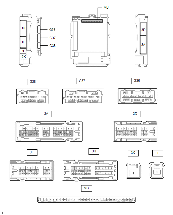
(a) Disconnect the instrument panel junction block assembly and main body ECU (multiplex network body ECU) connectors.
(b) Measure the voltage and resistance according to the value(s) in the table below.
| Terminal No. (Symbol) | Wiring Color | Terminal Description | Condition | Specified Condition |
|---|---|---|---|---|
| 3D-3 - Body ground | LA - Body ground | Ground | Always | Below 1 Ω |
| 3F-1 - Body ground | LG - Body ground | Battery power supply | Always | 11 to 14 V |
| 3K-1 - Body ground | B - Body ground | Battery power supply | Always | 11 to 14 V |
(c) Connect the instrument panel junction block assembly and main body ECU (multiplex network body ECU) connectors.
(d) Measure the voltage and resistance, and check for pulses according to the value(s) in the table below.
| Terminal No. (Symbol) | Wiring Color | Terminal Description | Condition | Specified Condition |
|---|---|---|---|---|
| 3A-40 - Body ground | LA-G - Body ground | BKUP LP relay drive output | Engine switch off | Below 1 V |
| Engine switch on (ACC) | 11 to 14 V | |||
| 3F-19 - Body ground | BE - Body ground | BKUP LP relay drive output | Engine switch off, reverse (R) not selected | Below 1 V |
| Engine switch on (IG), reverse (R) selected | 11 to 14 V | |||
| 3F-23 - Body ground | L - Body ground | BKUP LP relay drive output | Engine switch off | Below 1 V |
| Engine switch on (IG) | 11 to 14 V | |||
| 3F-31 - Body ground | V - Body ground | H-LP LH relay drive output |
| Below 1 V |
| 11 to 14 V | |||
| 3H-10 - Body ground | LG - Body ground | Back-up lights drive output | Engine switch off, reverse (R) not selected | Below 1 V |
| Engine switch on (IG), reverse (R) selected | 11 to 14 V | |||
| 3H-30 - Body ground | B - Body ground | Taillights, rear side marker lights and license plate lights drive output | Taillights on | 11 to 14 V |
| Taillights off | Below 1 V | |||
| G36-19 (GND2) - Body ground | W-B - Body ground | Ground | Always | Below 1 Ω |
| G37-12 (HRY2) - Body ground | BE - Body ground | H-LP RH relay drive output |
| Below 1 V |
| 11 to 14 V | |||
| G37-16 (HEAD) - Body ground | LG - Body ground | Light control switch head position input | Light control switch in head position | Below 1 V |
| Light control switch not in head position | 11 to 14 V | |||
| G37-23 (CLTB) - G37-25 (CLTE) | L - GR | Automatic light control sensor power supply output | Engine switch off | Below 1 V |
| Engine switch on (IG) | 11 to 14 V | |||
| G37-24 (CLTS) - Body ground | LG - Body ground | Automatic light control sensor signal input | Engine switch off | Below 1 V |
| Engine switch on (IG) | Pulse generation (See waveform 1) | |||
| G38-2 (MILE) - Body ground | B - Body ground | Outside handle foot lights drive output | Outside handle foot light illuminates | 11 to 14 V |
| Outside handle foot light off | Below 3 V |
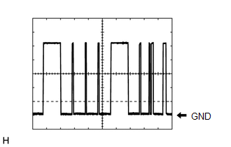
(1) Waveform 1
| Item | Content |
|---|---|
| Tester Connection | G37-24 (CLTS) - Body ground |
| Tool setting | 2 V/DIV., 10 ms./DIV. |
| Condition | Engine switch on (IG) |
HINT:
The communication waveform changes according to the surrounding brightness.
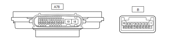
CHECK HEADLIGHT ECU SUB-ASSEMBLY LH (for LED Type Turn Signal Light)

(a) Disconnect the A78 headlight ECU sub-assembly LH connector.
(b) Measure the voltage and resistance on the wire harness side connector according to the value(s) in the table below.
| Terminal No. (Symbol) | Wiring Color | Terminal Description | Condition | Specified Condition |
|---|---|---|---|---|
| A78-4 (IG) - Body ground | B - Body ground | Ignition power supply | Engine switch off | Below 1 V |
| Engine switch on (IG) | 11 to 14 V | |||
| A78-12 (GND) - Body ground | W-B - Body ground | Ground | Always | Below 1 Ω |
| A78-13 (ECUB) - Body ground | B - Body ground | Battery power supply |
| Below 1 V |
| 9.5 to 14 V |
(c) Connect the A78 headlight ECU sub-assembly LH connector.
HINT:
- Since the A78 headlight ECU sub-assembly LH connector is a waterproof type connector, the voltage and pulses cannot be checked directly. The values listed are for reference only.
- Since the B and C headlight ECU sub-assembly LH connectors are connected inside the headlight assembly, the voltage and pulses cannot be checked directly. The values listed are for reference only.
(d) Measure the voltage and check of pulses according to the value(s) in the table below.
| Terminal No. (Symbol) | Wiring Color | Terminal Description | Condition | Specified Condition |
|---|---|---|---|---|
| A78-11 (TNS) - Body ground | LG - Body ground | Front turn signal light signal input | Engine switch on (IG), front turn signal light off | Below 1 V |
| Engine switch on (IG), front turn signal light blinking | 11 to 14 V ←→ Below 1 V | |||
| A78-16 (SBR) - A78-15 (SGR) | LG - G | Rear height control sensor sub-assembly LH power supply | Engine switch on (IG) | 4.75 to 5.25 V |
| A78-17 (SHRL) - A78-15 (SGR) | BE - G | Rear height control sensor sub-assembly LH signal input | Engine switch on (IG), vehicle unloaded, vehicle stopped | Approximately 2.5 V (value decreases as the front of the vehicle is raised) |
| A78-19 (LINS) - Body ground | P - Body ground | LIN communication line | Engine switch off | Below 1 V |
| Engine switch on (IG) | Pulse generation | |||
| A78-20 (LINL) - Body ground | W - Body ground | LIN communication line | Engine switch off | Below 1 V |
| Engine switch on (IG) | Pulse generation | |||
| A78-23 (CANL) - Body ground | W - Body ground | CAN communication line | Engine switch off | Below 1 V |
| Engine switch on (IG) | Pulse generation | |||
| A78-24 (CANH) - Body ground | R - Body ground | CAN communication line | Engine switch off | Below 1 V |
| Engine switch on (IG) | Pulse generation | |||
| B-2 (LOLED2) - B-3 (LOLED1) | - | Low beam headlights drive output | Low beam headlights off | Below 1 V |
| Low beam headlights on | 24.2 to 35.4 V | |||
| B-4 (FANB) - B-14 (FANG) | - | Headlight fan power source | Low beam headlights off | Below 1 V |
| Low beam headlights on | 4.75 to 5.25 V | |||
| B-6 (HILED2) - B-5 (HILED1) | - | Cornering lights drive output | Cornering lights off | Below 1 V |
| Cornering lights on | 8.05 to 11.8 V | |||
| B-9 (ACTBI) - B-17 (ACTGI) | - | Headlight swivel motor and headlight leveling motor power source | Engine switch off | Below 1 V |
| Engine switch on (IG) | 11 to 14 V | |||
| B-10 (DRL/CLL+) - B-1 (DRL/CLL-) | - | Parking lights/daytime running lights power source | Parking lights and daytime running lights off | Below 1 V |
| Parking lights and daytime running lights on | 11 to 14 V | |||
| B-15 (FANP) - B-14 (FANG) | - | Headlight fan control signal input | Low beam headlights off | Below 1 V |
| Low beam headlights on | Pulse generation | |||
| B-16 (PWM1) - B-1 (DRL/CLL-) | - | Parking lights/daytime running lights control signal output | Parking lights and daytime running lights off | Below 1 V |
| Parking lights and daytime running lights on | Pulse generation | |||
| B-18 (FSML+) - B-12 (FSML-) | - | Front side marker lights drive output | Front side marker lights off | Below 1 V |
| Front side marker lights on | 11 to 14 V | |||
| B-19 (HI_SOL+) - B-11 (HI_SOL-) | - | High beam headlights drive output | High beam headlights off | Below 1 V |
| High beam headlights on | 11 to 14 V | |||
| B-20 (TURN+) - B-13 (TURN-) | - | Front turn signal light signal output | Engine switch on (IG), front turn signal light off | Below 1 V |
| Engine switch on (IG), front turn signal light blinking | 11 to 14 V ←→ Below 1 V | |||
| C-4 (LINSI) - Body ground | - | LIN communication line | Engine switch off | Below 1 V |
| Engine switch on (IG) | Pulse generation | |||
| C-13 (LINLI) - Body ground | - | LIN communication line | Engine switch off | Below 1 V |
| Engine switch on (IG) | Pulse generation |
CHECK HEADLIGHT ECU SUB-ASSEMBLY LH (for Bulb Type Turn Signal Light)
(a) Disconnect the A78 headlight ECU sub-assembly LH connector.
(b) Measure the voltage and resistance on the wire harness side connector according to the value(s) in the table below.
| Terminal No. (Symbol) | Wiring Color | Terminal Description | Condition | Specified Condition |
|---|---|---|---|---|
| A78-4 (IG) - Body ground | B - Body ground | Ignition power supply | Engine switch off | Below 1 V |
| Engine switch on (IG) | 11 to 14 V | |||
| A78-12 (GND) - Body ground | W-B - Body ground | Ground | Always | Below 1 Ω |
| A78-13 (ECUB) - Body ground | B - Body ground | Battery power supply |
| Below 1 V |
| 9.5 to 14 V |
(c) Connect the A78 headlight ECU sub-assembly LH connector.
HINT:
- Since the A78 headlight ECU sub-assembly LH connector is a waterproof type connector, the voltage and pulses cannot be checked directly. The values listed are for reference only.
- Since the B headlight ECU sub-assembly LH connector are connected inside the headlight assembly, the voltage and pulses cannot be checked directly. The values listed are for reference only.
(d) Measure the voltage and check of pulses according to the value(s) in the table below.
| Terminal No. (Symbol) | Wiring Color | Terminal Description | Condition | Specified Condition |
|---|---|---|---|---|
| A78-11 (TNS) - Body ground | LG - Body ground | Front turn signal light signal input | Engine switch on (IG), front turn signal light off | Below 1 V |
| Engine switch on (IG), front turn signal light blinking | 11 to 14 V ←→ Below 1 V | |||
| A78-23 (CANL) - Body ground | W - Body ground | CAN communication line | Engine switch off | Below 1 V |
| Engine switch on (IG) | Pulse generation | |||
| A78-24 (CANH) - Body ground | R - Body ground | CAN communication line | Engine switch off | Below 1 V |
| Engine switch on (IG) | Pulse generation | |||
| B-2 (LOLED2) - B-3 (LOLED1) | - | Low beam headlights drive output | Low beam headlights off | Below 1 V |
| Low beam headlights on | 10 to 19 V | |||
| B-6 (HILED2) - B-5 (HILED1) | - | Cornering lights drive output | Cornering lights off | Below 1 V |
| Cornering lights on | 8.05 to 11.8 V | |||
| B-10 (DRL/CLL+) - B-1 (DRL/CLL-) | - | Parking lights/daytime running lights power source | Parking lights and daytime running lights off | Below 1 V |
| Parking lights and daytime running lights on | 11 to 14 V | |||
| B-16 (PWM1) - B-1 (DRL/CLL-) | - | Parking lights/daytime running lights control signal output | Parking lights and daytime running lights off | Below 1 V |
| Parking lights and daytime running lights on | Pulse generation | |||
| B-18 (FSML+) - B-12 (FSML-) | - | Front side marker lights drive output | Front side marker lights off | Below 1 V |
| Front side marker lights on | 11 to 14 V | |||
| B-19 (HI_SOL+) - B-11 (HI_SOL-) | - | High beam headlights drive output | High beam headlights off | Below 1 V |
| High beam headlights on | 11 to 14 V | |||
| B-20 (TURN+) - B-13 (TURN-) | - | Front turn signal light signal output | Engine switch on (IG), front turn signal light off | Below 1 V |
| Engine switch on (IG), front turn signal light blinking | 11 to 14 V ←→ Below 1 V |
CHECK HEADLIGHT ECU SUB-ASSEMBLY RH (for LED Type Turn Signal Light)
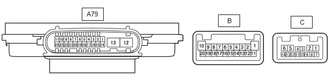
(a) Disconnect the A79 headlight ECU sub-assembly RH connector.
(b) Measure the voltage and resistance on the wire harness side connector according to the value(s) in the table below.
| Terminal No. (Symbol) | Wiring Color | Terminal Description | Condition | Specified Condition |
|---|---|---|---|---|
| A79-4 (IG) - Body ground | B - Body ground | Ignition power supply | Engine switch off | Below 1 V |
| Engine switch on (IG) | 11 to 14 V | |||
| A79-12 (GND) - Body ground | W-B - Body ground | Ground | Always | Below 1 Ω |
| A79-13 (ECUB) - Body ground | R - Body ground | Battery power supply |
| Below 1 V |
| 9.5 to 14 V |
(c) Connect the A79 headlight ECU sub-assembly RH connector.
HINT:
- Since the A79 headlight ECU sub-assembly RH connector is a waterproof type connector, the voltage and pulses cannot be checked directly. The values listed are for reference only.
- Since the B and C headlight ECU sub-assembly RH connectors are connected inside the headlight assembly, the voltage and pulses cannot be checked directly. The values listed are for reference only.
(d) Measure the voltage and check of pulses according to the value(s) in the table below.
| Terminal No. (Symbol) | Wiring Color | Terminal Description | Condition | Specified Condition |
|---|---|---|---|---|
| A79-11 (TNS) - Body ground | G - Body ground | Front turn signal light signal input | Engine switch on (IG), front turn signal light off | Below 1 V |
| Engine switch on (IG), front turn signal light blinking | 11 to 14 V ←→ Below 1 V | |||
| A79-19 (LINS) - Body ground | P - Body ground | LIN communication line | Engine switch off | Below 1 V |
| Engine switch on (IG) | Pulse generation | |||
| A79-20 (LINL) - Body ground | W - Body ground | LIN communication line | Engine switch off | Below 1 V |
| Engine switch on (IG) | Pulse generation | |||
| A79-23 (CANL) - Body ground | W - Body ground | CAN communication line | Engine switch off | Below 1 V |
| Engine switch on (IG) | Pulse generation | |||
| A79-24 (CANH) - Body ground | L - Body ground | CAN communication line | Engine switch off | Below 1 V |
| Engine switch on (IG) | Pulse generation | |||
| B-2 (LOLED2) - B-3 (LOLED1) | - | Low beam headlights drive output | Low beam headlights off | Below 1 V |
| Low beam headlights on | 24.2 to 35.4 V | |||
| B-4 (FANB) - B-14 (FANG) | - | Headlight fan power source | Low beam headlights off | Below 1 V |
| Low beam headlights on | 4.75 to 5.25 V | |||
| B-6 (HILED2) - B-5 (HILED1) | - | Cornering lights drive output | Cornering lights off | Below 1 V |
| Cornering lights on | 8.05 to 11.8 V | |||
| B-9 (ACTBI) - B-17 (ACTGI) | - | Headlight swivel motor and headlight leveling motor power source | Engine switch off | Below 1 V |
| Engine switch on (IG) | 11 to 14 V | |||
| B-10 (DRL/CLL+) - B-1 (DRL/CLL-) | - | Parking lights/daytime running lights power source | Parking lights and daytime running lights off | Below 1 V |
| Parking lights and daytime running lights on | 11 to 14 V | |||
| B-15 (FANP) - B-14 (FANG) | - | Headlight fan control signal input | Low beam headlights off | Below 1 V |
| Low beam headlights on | Pulse generation | |||
| B-16 (PWM1) - B-1 (DRL/CLL-) | - | Parking lights/daytime running lights control signal output | Parking lights and daytime running lights off | Below 1 V |
| Parking lights and daytime running lights on | Pulse generation | |||
| B-18 (FSML+) - B-12 (FSML-) | - | Front side marker lights drive output | Front side marker lights off | Below 1 V |
| Front side marker lights on | 11 to 14 V | |||
| B-19 (HI_SOL+) - B-11 (HI_SOL-) | - | High beam headlights drive output | High beam headlights off | Below 1 V |
| High beam headlights on | 11 to 14 V | |||
| B-20 (TURN+) - B-13 (TURN-) | - | Front turn signal light signal output | Engine switch on (IG), front turn signal light off | Below 1 V |
| Engine switch on (IG), front turn signal light blinking | 11 to 14 V ←→ Below 1 V | |||
| C-4 (LINSI) - Body ground | - | LIN communication line | Engine switch off | Below 1 V |
| Engine switch on (IG) | Pulse generation | |||
| C-13 (LINLI) - Body ground | - | LIN communication line | Engine switch off | Below 1 V |
| Engine switch on (IG) | Pulse generation |
CHECK HEADLIGHT ECU SUB-ASSEMBLY RH (for Bulb Type Turn Signal Light)

(a) Disconnect the A79 headlight ECU sub-assembly RH connector.
(b) Measure the voltage and resistance on the wire harness side connector according to the value(s) in the table below.
| Terminal No. (Symbol) | Wiring Color | Terminal Description | Condition | Specified Condition |
|---|---|---|---|---|
| A79-4 (IG) - Body ground | B - Body ground | Ignition power supply | Engine switch off | Below 1 V |
| Engine switch on (IG) | 11 to 14 V | |||
| A79-12 (GND) - Body ground | W-B - Body ground | Ground | Always | Below 1 Ω |
| A79-13 (ECUB) - Body ground | R - Body ground | Battery power supply |
| Below 1 V |
| 9.5 to 14 V |
(c) Connect the A79 headlight ECU sub-assembly RH connector.
HINT:
- Since the A79 headlight ECU sub-assembly RH connector is a waterproof type connector, the voltage and pulses cannot be checked directly. The values listed are for reference only.
- Since the B headlight ECU sub-assembly RH connector are connected inside the headlight assembly, the voltage and pulses cannot be checked directly. The values listed are for reference only.
(d) Measure the voltage and check of pulses according to the value(s) in the table below.
| Terminal No. (Symbol) | Wiring Color | Terminal Description | Condition | Specified Condition |
|---|---|---|---|---|
| A79-11 (TNS) - Body ground | G - Body ground | Front turn signal light signal input | Engine switch on (IG), front turn signal light off | Below 1 V |
| Engine switch on (IG), front turn signal light blinking | 11 to 14 V ←→ Below 1 V | |||
| A79-23 (CANL) - Body ground | W - Body ground | CAN communication line | Engine switch off | Below 1 V |
| Engine switch on (IG) | Pulse generation | |||
| A79-24 (CANH) - Body ground | L - Body ground | CAN communication line | Engine switch off | Below 1 V |
| Engine switch on (IG) | Pulse generation | |||
| B-2 (LOLED2) - B-3 (LOLED1) | - | Low beam headlights drive output | Low beam headlights off | Below 1 V |
| Low beam headlights on | 10 to 19 V | |||
| B-6 (HILED2) - B-5 (HILED1) | - | Cornering lights drive output | Cornering lights off | Below 1 V |
| Cornering lights on | 8.05 to 11.8 V | |||
| B-10 (DRL/CLL+) - B-1 (DRL/CLL-) | - | Parking lights/daytime running lights power source | Parking lights and daytime running lights off | Below 1 V |
| Parking lights and daytime running lights on | 11 to 14 V | |||
| B-16 (PWM1) - B-1 (DRL/CLL-) | - | Parking lights/daytime running lights control signal output | Parking lights and daytime running lights off | Below 1 V |
| Parking lights and daytime running lights on | Pulse generation | |||
| B-18 (FSML+) - B-12 (FSML-) | - | Front side marker lights drive output | Front side marker lights off | Below 1 V |
| Front side marker lights on | 11 to 14 V | |||
| B-19 (HI_SOL+) - B-11 (HI_SOL-) | - | High beam headlights drive output | High beam headlights off | Below 1 V |
| High beam headlights on | 11 to 14 V | |||
| B-20 (TURN+) - B-13 (TURN-) | - | Front turn signal light signal output | Engine switch on (IG), front turn signal light off | Below 1 V |
| Engine switch on (IG), front turn signal light blinking | 11 to 14 V ←→ Below 1 V |
CHECK COMBINATION METER ASSEMBLY
Click here .gif)
CHECK FORWARD RECOGNITION CAMERA
Click here
CHECK STEERING SENSOR
Click here
READ NEXT:
 Dtc Check / Clear
DTC CHECK / CLEAR CHECK FOR DTC (MAIN BODY) (a) Connect the Techstream to the DLC3. (b) Turn the engine switch on (IG). (c) Turn the Techstream on. (d) Enter the following menus: Body Electrical / Mai
Freeze Frame Data
FREEZE FRAME DATA FREEZE FRAME DATA (a) Whenever a lighting system DTC is stored, the headlight ECU sub-assembly and forward recognition camera stores the current vehicle state as freeze frame data. C
Data List / Active Test
DATA LIST / ACTIVE TEST DATA LIST NOTICE: In the table below, the values listed under "Normal Condition" are reference values. Do not depend solely on these reference values when deciding whether a pa
SEE MORE:
Removal
REMOVAL CAUTION / NOTICE / HINT The necessary procedures (adjustment, calibration, initialization or registration) that must be performed after parts are removed and installed, or replaced during headlight ECU sub-assembly removal/installation are shown below. Necessary Procedure After Parts Removed
Pressure Control Solenoid "B" Actuator Stuck Off (P07757F)
DESCRIPTION Based on signals from the transmission revolution sensors (NT and NC), the actual gear is detected. The ECM compares the actual gear with the shift schedule in the ECM memory to detect mechanical malfunctions of the solenoid valves, transmission valve body assembly and automatic transaxl
