Lexus ES: Terminals Of Ecu
TERMINALS OF ECU
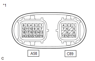
| *1 | Inverter with Converter Assembly |
HINT:
Since the inverter with converter assembly uses waterproof connectors, the voltage and waveforms cannot be inspected directly. Standard voltage readings and waveforms are indicated for reference only.
Inverter with Converter Assembly| Terminal No. (Symbol) | Wiring Color | Input/Output | Terminal Description | Condition | Standard Condition |
|---|---|---|---|---|---|
| A58-1 (CANH) - A58-24 (GND1) | V - W-B | Input/Output | CAN communication signal | Power switch on (IG) | Pulse generation (Waveform 1) |
| A58-5 (+B2) - A58-24 (GND1) | GR - W-B | Input | Motor generator control ECU (MG ECU) power source | Power switch on (IG) | 11 to 14 V |
| A58-6 (+B) - A58-24 (GND1) | W - W-B | Input | Motor generator control ECU (MG ECU) power source | Power switch on (IG) | 11 to 14 V |
| A58-7 (CANL) - A58-24 (GND1) | W - W-B | Input/Output | CAN communication signal | Power switch on (IG) | Pulse generation (Waveform 1) |
| A58-10 (GI) - A58-24 (GND1) | W - W-B | Input | Camshaft position sensor signal | Power switch on (READY), engine running | Pulse generation (Waveform 2) |
| A58-12 (IGCT) - A58-24 (GND1) | BE - W-B | Input | Motor generator control ECU (MG ECU) power source | Power switch on (IG) | 11 to 14 V |
| A58-17 (NE) - A58-24 (GND1) | B - W-B | Input | Crankshaft position sensor signal | Power switch on (READY), engine running | Pulse generation (Waveform 3) |
| A58-19 (HMCL) - A58-24 (GND1) | W - W-B | Input/Output | Communication signal | Power switch on (IG) | Pulse generation (Waveform 4) |
| A58-20 (HMCH) - A58-24 (GND1) | B - W-B | Input/Output | Communication signal | Power switch on (IG) | Pulse generation (Waveform 4) |
| A58-22 (HSDN) - A58-24 (GND1) | W - W-B | Input | MG shutdown signal | Power switch on (READY) | 0 to 1 V |
| C89-1 (MSN) - C89-2 (MSNG) | G - Y | Input | Motor resolver signal | Motor resolver running | Pulse generation (Waveform 5) |
| C89-3 (MCSG) - C89-4 (MCS) | B - L | Input | Motor resolver signal | Motor resolver running | Pulse generation (Waveform 5) |
| C89-5 (MRF) - C89-6 (MRFG) | W - R | Output | Motor resolver reference signal | Motor resolver running | Pulse generation (Waveform 5) |
| C89-8 (GRF) - C89-9 (GRFG) | SB - V | Output | Generator resolver reference signal | Generator resolver running | Pulse generation (Waveform 6) |
| C89-10 (GSN) - C89-11 (GSNG) | GR - P | Input | Generator resolver signal | Generator resolver running | Pulse generation (Waveform 6) |
| C89-12 (GCSG) - C89-13 (GCS) | BR - LG | Input | Generator resolver signal | Generator resolver running | Pulse generation (Waveform 6) |
NOTICE:
Do not measure the voltage or waveform on the sealed side of the inverter with converter assembly connector. Doing so may damage the connector because the connector is waterproof.
Oscilloscope waveforms
HINT:
Oscilloscope waveforms shown in the illustrations are examples for reference only. Noise, chattering, etc. are not shown.
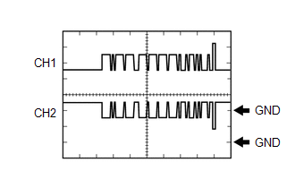
(a) Waveform 1 (CAN communication signal)
| Item | Content |
|---|---|
| Terminal | CH1: A58-1 (CANH) - A58-24 (GND1) CH2: A58-7 (CANL) - A58-24 (GND1) |
| Equipment Setting | 1 V/DIV., 50 μs./DIV. |
| Condition | Power switch on (IG) |
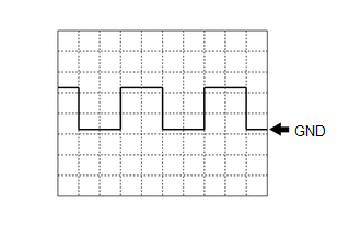
(b) Waveform 2 (camshaft position sensor signal)
| Item | Content |
|---|---|
| Terminal | A58-10 (GI) - A58-24 (GND1) |
| Equipment Setting | 5 V/DIV., 20 ms./DIV. |
| Condition | Power switch on (READY), engine running |
HINT:
The wavelength becomes shorter as the engine speed increases.
(c) Waveform 3 (crankshaft position sensor signal)
| Item | Content |
|---|---|
| Terminal | A58-17 (NE) - A58-24 (GND1) |
| Equipment Setting | 5 V/DIV., 20 ms./DIV. |
| Condition | Power switch on (READY), engine running |
HINT:
The wavelength becomes shorter as the engine speed increases.
(d) Waveform 4 (communication signal)
| Item | Content |
|---|---|
| Terminal | CH1: A58-19 (HMCL) - A58-24 (GND1) CH2: A58-20 (HMCH) - A58-24 (GND1) |
| Equipment Setting | 1 V/DIV., 50 μs./DIV. |
| Condition | Power switch on (IG) |
HINT:
The waveform will vary depending on the content of the digital communication (digital signal).
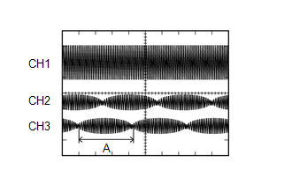
(e) Waveform 5 (motor resolver signal)
| Item | Content |
|---|---|
| Terminal | CH1: C89-5 (MRF) - C89-6 (MRFG) CH2: C89-1 (MSN) - C89-2 (MSNG) CH3: C89-4 (MCS) - C89-3 (MCSG) |
| Equipment Setting | CH1: 10 V/DIV., 1 ms./DIV. CH2: 5 V/DIV., 1 ms./DIV. CH3: 5 V/DIV., 1 ms./DIV. |
| Condition | Motor resolver running |
HINT:
The width indicated by (A) becomes shorter as the rotor speed increases.
(f) Waveform 6 (generator resolver signal)
| Item | Content |
|---|---|
| Terminal | CH1: C89-8 (GRF) - C89-9 (GRFG) CH2: C89-10 (GSN) - C89-11 (GSNG) CH3: C89-13 (GCS) - C89-12 (GCSG) |
| Equipment Setting | CH1: 10 V/DIV., 1 ms./DIV. CH2: 5 V/DIV., 1 ms./DIV. CH3: 5 V/DIV., 1 ms./DIV. |
| Condition | Generator resolver running |
HINT:
The width indicated by (A) becomes shorter as the rotor speed increases.
READ NEXT:
 Diagnosis System
DIAGNOSIS SYSTEM DESCRIPTION (a) The motor generator control ECU (MG ECU) (inverter with converter assembly) has a self-diagnosis system. If the motor generator control ECU (MG ECU), motor generator s
Dtc Check / Clear
DTC CHECK / CLEAR CHECK FOR DTC (a) Connect the Techstream to the DLC3. (b) Turn the power switch on (IG). (c) Turn the Techstream on. (d) Enter the following menus: Powertrain / Motor Generator / Tro
Freeze Frame Data
FREEZE FRAME DATA FREEZE FRAME DATA HINT: The motor generator control ECU records vehicle and driving condition information as freeze frame data the moment a DTC is stored. It can be used for estimati
SEE MORE:
System Description
SYSTEM DESCRIPTION FUNCTION OF COMPONENTS (a) The parking support brake system consists of the following components: Component Function Clearance Warning ECU Assembly
Sends the drive force request signals and control status signals to the ECM and skid control ECU.
Sends the multi-inf
Removal
REMOVAL CAUTION / NOTICE / HINT The necessary procedures (adjustment, calibration, initialization, or registration) that must be performed after parts are removed and installed, or replaced during automatic transaxle assembly removal/installation are shown below. Necessary Procedures After Parts Rem
