Lexus ES: Terminals Of Ecm
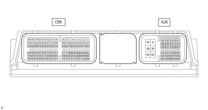
TERMINALS OF ECM
HINT:
The standard voltage, resistance and waveform between each pair of the ECM terminals is shown in the table below. The appropriate conditions for checking each pair of the terminals is also indicated. The result of checks should be compared with the standard voltage, resistance and waveform for each pair of the terminals as displayed in the Specified Condition column. The illustration above can be used as a reference to identify the ECM terminal locations.
| Terminal No. (Symbol) | Wiring Color | Terminal Description | Condition | Specified Condition |
|---|---|---|---|---|
| A26-1 (BATT) - A26-10 (E1) | G - W-B |
| Always | 11 to 16 V |
| A26-2 (IGSW) - A26-10 (E1) | B - W-B | Power switch signal | Power switch on (IG) | 11 to 14 V |
| A26-3 (VPMP) - A26-10 (E1) | L - W-B | Vent valve (built into canister pump module) | Power switch on (IG) | 11 to 14 V |
| A26-5 (MPMP) - A26-10 (E1) | V - W-B | Leak detection pump (canister pump module) | Leak detection pump off | Below 3 V |
| Leak detection pump on | 11 to 14 V | |||
| A26-6 (FPC) - A26-10 (E1) | R - W-B | Fuel pump control | Engine stopped, power switch on (IG) | Below 1.5 V |
| A26-7 (CAN+) - A26-10 (E1) | P - W-B | CAN communication line | Engine stopped, power switch on (IG) | Pulse generation (See waveform 1) |
| A26-8 (CANH) - A26-10 (E1) | B - W-B | CAN communication line | Engine stopped, power switch on (IG) | Pulse generation (See waveform 1) |
| A26-9 (+B) - A26-10 (E1) | L - W-B | Power source of ECM | Power switch on (IG) | 11 to 14 V |
| A26-10 (E1) - Body ground | W-B - - | Ground | Always | Below 1 Ω |
| A26-12 (CCV2) - A26-10 (E1) | BE - W-B | Fuel vapor containment valve assembly signal | Fuel vapor containment valve assembly on (open) | Below 1.0 V |
| Fuel vapor containment valve assembly off (closed) | 11 to 14 V | |||
| A26-15 (MREL) - A26-10 (E1) | W - W-B | EFI-MAIN NO. 1 relay operation signal | Power switch on (IG) | Below 1.5 V |
| A26-16 (NEO) - A26-10 (E1) | B - W-B | Crankshaft revolution signal | Idling with warm engine | Pulse generation (See waveform 2) |
| A26-17 (CAN-) - A26-10 (E1) | W - W-B | CAN communication line | Engine stopped, power switch on (IG) | Pulse generation (See waveform 3) |
| A26-18 (CANL) - A26-10 (E1) | W - W-B | CAN communication line | Engine stopped, power switch on (IG) | Pulse generation (See waveform 3) |
| A26-24 (G2O) - A26-10 (E1) | W - W-B | Camshaft revolution signal | Idling with warm engine | Pulse generation (See waveform 4) |
| A26-31 (LIDO) - A26-10 (E1) | GR - W-B | Fuel lid courtesy switch signal | Fuel lid closed | Below 1.0 V |
| Fuel lid open | 11 to 14 V | |||
| A26-32 (RFC) - A26-10 (E1) | LG - W-B | Cooling fan control signal | Power switch on (IG), A/C switch on (max cool) | Pulse generation (See waveform 5) |
| A26-34 (IREL) - A26-10 (E1) | P - W-B | D INJ relay operation signal | Power switch on (IG) | 11 to 14 V |
| A26-35 (+B2) - A26-10 (E1) | L - W-B | Power source of ECM | Power switch on (IG) | 11 to 14 V |
| A26-36 (E2) - Body ground | W-B - - | Ground | Always | Below 1 Ω |
| A26-38 (FUEL) - A26-10 (E1) | B - W-B | Fuel lid opener switch signal | Fuel lid opener switch pressed | Below 1.0 V |
| Fuel lid opener switch not pressed | 4.5 to 5.5 V | |||
| A26-45 (EC) - Body ground | W-B - - | Ground | Always | Below 1 Ω |
| A26-41 (LSTM) - A26-10 (E1) | W - W-B | Fuel lid operation signal for combination meter assembly | Multi-information display displaying "Close Fuel Lid" | Pulse generation (See waveform 6) |
| Multi-information display displaying "Ready to Refuel" | Pulse generation (See waveform 7) | |||
| Power switch on (IG) | 11 to 14 V | |||
| A26-44 (FREL) - A26-10 (E1) | Y - W-B | Fuel lid lock with motor assembly operation signal | Fuel lid lock with motor assembly operating | Below 1.0 V |
| Fuel lid lock with motor assembly not operating | 11 to 14 V | |||
| A26-48 (VCPP) - A26-49 (EPPM) | V - LG | Power source for canister pressure sensor (specific voltage) | Power switch on (IG) | 4.5 to 5.5 V |
| A26-50 (PPMP) - A26-49 (EPPM) | BE - LG | Canister pressure sensor (built into canister pump module) | Power switch on (IG) | 3.0 to 3.6 V |
| A26-53 (+BD1) - A26-10 (E1) | W - W-B | Power source of ECU (injector driver) | Power switch on (IG) | 11 to 14 V |
| A26-54 (E1D1) - Body ground | W-B - - | Ground | Always | Below 1 Ω |
| A26-57 (VPTK) - A26-56 (EPTK) | L - G | Power source of fuel tank pressure sensor (specific voltage) | Engine stopped, power switch on (IG) | 4.75 to 5.25 V |
| A26-55 (PTNK) - A26-56 (EPTK) | R - G | Fuel tank pressure sensor signal | Engine stopped, power switch on (IG) | 0.27 to 4.73 V |
| C88-1 (M-) - A26-10 (E1) | L - W-B | Throttle actuator operation signal (negative signal) | Idling with warm engine | Pulse generation (See waveform 8) |
| C88-2 (M+) - A26-10 (E1) | B - W-B | Throttle actuator operation signal (positive terminal) | Idling with warm engine | Pulse generation (See waveform 9) |
| C88-3 (EGA+) - A26-10 (E1) | R - W-B | EGR valve assembly operation signal | Idling with warm engine | Pulse generation (See waveform 10) |
| C88-4 (EGA-) - A26-10 (E1) | L - W-B | EGR valve assembly operation signal | Idling with warm engine | Pulse generation (See waveform 10) |
| C88-5 (EGB-) - A26-10 (E1) | V - W-B | EGR valve assembly operation signal | Idling with warm engine | Pulse generation (See waveform 10) |
| C88-6 (EGB+) - A26-10 (E1) | GR - W-B | EGR valve assembly operation signal | Idling with warm engine | Pulse generation (See waveform 10) |
| C88-7 (HTHM) - A26-10 (E1) | LA-G - W-B | Thermostat heater operation signal | Power switch on (IG) | 11 to 14 V |
| C88-8 (HA1B) - A26-10 (E1) | R - W-B | Air fuel ratio sensor (sensor 2) heater operation signal | Power switch on (IG) | 11 to 14 V |
| Idling with cold engine | Pulse generation (See waveform 11) | |||
| C88-9 (HA1A) - A26-10 (E1) | L - W-B | Air fuel ratio sensor (sensor 1) heater operation signal | Power switch on (IG) | 11 to 14 V |
| Idling with cold engine | Pulse generation (See waveform 12) | |||
| C88-10 (#2D-) - A26-10 (E1) | G - W-B | Direct fuel injector assembly signal (No. 2 cylinder) | Idling with warm engine, Data List item "Injection Mode" displaying "Direct" | Pulse generation (See waveform 13) |
| C88-11 (#2D+) - A26-10 (E1) | L - W-B | Direct fuel injector assembly signal (No. 2 cylinder) | Idling with warm engine, Data List item "Injection Mode" displaying "Direct" | Pulse generation (See waveform 13) |
| C88-12 (#3D+) - A26-10 (E1) | W - W-B | Direct fuel injector assembly signal (No. 3 cylinder) | Idling with warm engine, Data List item "Injection Mode" displaying "Direct" | Pulse generation (See waveform 13) |
| C88-13 (#3D-) - A26-10 (E1) | R - W-B | Direct fuel injector assembly signal (No. 3 cylinder) | Idling with warm engine, Data List item "Injection Mode" displaying "Direct" | Pulse generation (See waveform 13) |
| C88-14 (#4D-) - A26-10 (E1) | V - W-B | Direct fuel injector assembly signal (No. 4 cylinder) | Idling with warm engine, Data List item "Injection Mode" displaying "Direct" | Pulse generation (See waveform 13) |
| C88-15 (#4D+) - A26-10 (E1) | P - W-B | Direct fuel injector assembly signal (No. 4 cylinder) | Idling with warm engine, Data List item "Injection Mode" displaying "Direct" | Pulse generation (See waveform 13) |
| C88-16 (#1D+) - A26-10 (E1) | W - W-B | Direct fuel injector assembly signal (No. 1 cylinder) | Idling with warm engine, Data List item "Injection Mode" displaying "Direct" | Pulse generation (See waveform 13) |
| C88-17 (#1D-) - A26-10 (E1) | BR - W-B | Direct fuel injector assembly signal (No. 1 cylinder) | Idling with warm engine, Data List item "Injection Mode" displaying "Direct" | Pulse generation (See waveform 13) |
| C88-18 (FP1-) - A26-10 (E1) | L - W-B | Fuel pump assembly (for high pressure side) signal | Idling with warm engine, Data List item "Injection Mode" displaying "Direct" | Pulse generation (See waveform 14) |
| C88-19 (FP1+) - A26-10 (E1) | G - W-B | Fuel pump assembly (for high pressure side) signal | Idling with warm engine, Data List item "Injection Mode" displaying "Direct" | Pulse generation (See waveform 14) |
| C88-20 (VOP-) - A26-10 (E1) | P - W-B | Oil pressure control valve operation signal | Idling with warm engine | Pulse generation (See waveform 15) |
| C88-21 (VOP+) - A26-10 (E1) | G - W-B | Oil pressure control valve operation signal | Idling with warm engine | Pulse generation (See waveform 15) |
| C88-26 (OE1+) - C88-25 (OE1-) | LA-B - LA-W | Cam timing oil control solenoid assembly operation signal | Idling | Pulse generation (See waveform 16) |
| C88-28 (EDT1) - A26-10 (E1) | P - W-B | Cam timing control motor with EDU assembly signal | Idling with warm engine | Pulse generation (See waveform 17) |
| C88-42 (WSV1) - A26-10 (E1) | LA-W - W-B | Flow shutting valve operation signal | Power switch on (IG) | 11 to 14 V |
| C88-46 (IGT4) - A26-10 (E1) | B - W-B | No. 4 ignition coil assembly signal (ignition signal) | Idling with warm engine | Pulse generation (See waveform 18) |
| C88-47 (IGT3) - A26-10 (E1) | P - W-B | No. 3 ignition coil assembly signal (ignition signal) | Idling with warm engine | Pulse generation (See waveform 18) |
| C88-48 (IGT2) - A26-10 (E1) | V - W-B | No. 2 ignition coil assembly signal (ignition signal) | Idling with warm engine | Pulse generation (See waveform 18) |
| C88-49 (IGT1) - A26-10 (E1) | W - W-B | No. 1 ignition coil assembly signal (ignition signal) | Idling with warm engine | Pulse generation (See waveform 18) |
| C88-50 (WPO) - A26-10 (E1) | LA-G - W-B | Water inlet housing with water pump sub-assembly signal | Idling with warm engine | Pulse generation (See waveform 19) |
| C88-51 (WPI) - A26-10 (E1) | LA-B - W-B | Water inlet housing with water pump sub-assembly signal | Idling with warm engine | Pulse generation (See waveform 20) |
| C88-66 (PRG) - A26-10 (E1) | P - W-B | Purge VSV operation signal | Power switch on (IG) | 11 to 14 V |
| Idling with warm engine, under purge control | Pulse generation (See waveform 21) | |||
| C88-70 (EMR1) - A26-10 (E1) | LG - W-B | Cam timing control motor with EDU assembly signal | Idling with warm engine | Pulse generation (See waveform 22) |
| C88-71 (EMF1) - A26-10 (E1) | B - W-B | Cam timing control motor with EDU assembly signal | Idling with warm engine | Below 5.0 V |
| C88-72 (EMD1) - A26-10 (E1) | L - W-B | Cam timing control motor with EDU assembly signal | Idling with warm engine | Pulse generation (See waveform 23) |
| C88-73 (#40) - A26-10 (E1) | P - W-B | Port fuel injector assembly signal (No. 4 cylinder) | Idling with warm engine (Data List item "Injection Mode" displaying "Port") | Pulse generation (See waveform 24) |
| C88-74 (#30) - A26-10 (E1) | W - W-B | Port fuel injector assembly signal (No. 3 cylinder) | Idling with warm engine (Data List item "Injection Mode" displaying "Port") | Pulse generation (See waveform 24) |
| C88-75 (#20) - A26-10 (E1) | G - W-B | Port fuel injector assembly signal (No. 2 cylinder) | Idling with warm engine (Data List item "Injection Mode" displaying "Port") | Pulse generation (See waveform 24) |
| C88-76 (#10) - A26-10 (E1) | B - W-B | Port fuel injector assembly signal (No. 1 cylinder) | Idling with warm engine (Data List item "Injection Mode" displaying "Port") | Pulse generation (See waveform 24) |
| C88-78 (VCVG) - A26-10 (E1) | R - W-B | Power source of mass air flow meter sub-assembly (specific voltage) | Power switch on (IG) | 4.8 to 5.2 V |
| C88-84 (VCPF) - A26-10 (E1) | LG - W-B | Power source of No. 2 fuel pressure sensor (for low pressure side) (specific voltage) | Power switch on (IG) | 4.75 to 5.25 V |
| C88-87 (VTA2) - C88-110 (ETA) | V - G | Throttle position sensor signal (for sensor malfunction detection) | Engine stopped, power switch on (IG), accelerator pedal fully released | 2.1 to 3.1 V |
| C88-88 (VCV1) - A26-10 (E1) | L - W-B | Power source of camshaft position sensor (for intake camshaft) (specific voltage) | Power switch on (IG) | 4.5 to 5.5 V |
| C88-90 (VV1+) - C88-89 (VV1-) | B - LG | Camshaft position sensor (for intake camshaft) signal | Idling with warm engine | Pulse generation (See waveform 25) |
| C88-91 (EV1+) - C88-114 (EV1-) | V - G | Camshaft position sensor (for exhaust camshaft) signal | Idling with warm engine | Pulse generation (See waveform 25) |
| C88-93 (NE+) - C88-115 (NE-) | L - P | Crankshaft position sensor signal | Idling with warm engine | Pulse generation (See waveform 26) |
| C88-94 (A1A-) - A26-10 (E1) | G - W-B | Air fuel ratio sensor (sensor 1) signal | Power switch on (IG) | 1.24 to 4.22 V |
| C88-95 (A1A+) - A26-10 (E1) | R - W-B | Air fuel ratio sensor (sensor 1) signal | Power switch on (IG) | 1.46 to 4.22 V |
| C88-97 (PR) - C88-96 (EPR) | L - V | Fuel pressure sensor (for high pressure side) signal | Idling with warm engine | 0.5 to 4.5 V |
| C88-98 (VCPR) - C88-96 (EPR) | LG - V | Power source of fuel pressure sensor (for high pressure side) (specific voltage) | Power switch on (IG) | 4.75 to 5.25 V |
| C88-99 (VCPE) - C88-100 (EPEO) | R - L | Power source of oil pressure and temperature sensor (specific voltage) | Power switch on (IG) | 4.5 to 5.5 V |
| C88-101 (VG) - C88-79 (E2G) | W - G | Mass air flow meter sub-assembly signal | Power switch on (IG) | Pulse generation (See waveform 27) |
| C88-102 (THA) - C88-79 (E2G) | V - G | Intake air temperature sensor signal | Idling, intake air temperature 0 to 80°C (32 to 176°F) | 0.5 to 3.4 V |
| C88-107 (PFL) - C88-61 (EPFL) | V - L | No. 2 fuel pressure sensor (for low pressure side) signal | Idling with warm engine | 0.75 to 4.5 V |
| C88-108 (VTA1) - C88-110 (ETA) | P - G | Throttle position sensor signal (for engine control) | Engine stopped, power switch on (IG), accelerator pedal fully released | 0.6 to 1.1 V |
| C88-109 (VCTA) - C88-110 (ETA) | R - G | Power source of throttle position sensor (specific voltage) | Engine stopped, power switch on (IG) | 4.5 to 5.5 V |
| C88-111 (KNK1) - C88-112 (EKNK) | B - W | Knock control sensor signal | Engine speed maintained at 2500 rpm after warming up engine | Pulse generation (See waveform 28) |
| C88-113 (VCE1) - A26-10 (E1) | L - W-B | Power source of camshaft position sensor (for exhaust camshaft) (specific voltage) | Power switch on (IG) | 4.5 to 5.5 V |
| C88-116 (VCNE) - A26-10 (E1) | V - W-B | Power source of crankshaft position sensor (specific voltage) | Power switch on (IG) | 4.5 to 5.5 V |
| C88-117 (A1B-) - A26-10 (E1) | W - W-B | Air fuel ratio sensor (sensor 2) signal | Power switch on (IG) | 1.17 to 4.49 V |
| C88-118 (A1B+) - A26-10 (E1) | B - W-B | Air fuel ratio sensor (sensor 2) signal | Power switch on (IG) | 1.53 to 5.96 V |
| C88-120 (PIM) - C88-119 (EPIM) | P - G | Manifold absolute pressure sensor signal | Power switch on (IG) | 3.0 to 4.5 V |
| C88-121 (VCPM) - C88-119 (EPIM) | B - G | Power source of manifold absolute pressure sensor (specific voltage) | Power switch on (IG) | 4.75 to 5.25 V |
| C88-122 (PEO) - C88-100 (EPEO) | W - L | Engine oil pressure sensor signal | Idling with warm engine | 0.5 to 4.5 V |
| C88-123 (THEO) - C88-100 (EPEO) | V - L | Engine oil temperature sensor signal | Power switch on (IG) | 0.14 to 4.93 V |
| C88-125 (THW) - C88-124 (ETHW) | L - P | Engine coolant temperature sensor signal | Idling, engine coolant temperature 75 to 100°C (167 to 212°F) | 0.2 to 1.0 V |
| C88-129 (THTW) - C88-130 (ETHT) | P - W | No. 2 engine coolant temperature sensor signal | Idling, engine coolant temperature 75 to 100°C (167 to 212°F) | 0.2 to 1.0 V |
WAVEFORM 1
.png) CAN Communication Signal (Reference)
CAN Communication Signal (Reference) | ECM Terminal Name | Between CANH and E1 Between CAN+ and E1 |
| Tester Range | 1 V/DIV., 10 μs./DIV. |
| Condition | Engine stopped, power switch on (IG) |
HINT:
The waveform varies depending on the CAN communication signal.
WAVEFORM 2
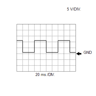 Crankshaft Revolution Signal from ECM to Inverter with Converter Assembly
 | ECM Terminal Name | Between NEO and E1 |
| Tester Range | 5 V/DIV., 20 ms./DIV. |
| Condition | Idling with warm engine |
HINT:
The wavelength becomes shorter as the engine speed increases.
WAVEFORM 3
.png) CAN Communication Signal (Reference)
CAN Communication Signal (Reference) | ECM Terminal Name | Between CANL and E1 Between CAN- and E1 |
| Tester Range | 1 V/DIV., 10 μs./DIV. |
| Condition | Engine stopped, power switch on (IG) |
HINT:
The waveform varies depending on the CAN communication signal.
WAVEFORM 4
 Camshaft Revolution Signal from ECM to Inverter with Converter Assembly
 | ECM Terminal Name | Between G2O and E1 |
| Tester Range | 5 V/DIV., 20 ms./DIV. |
| Condition | Idling with warm engine |
HINT:
The wavelength becomes shorter as the engine speed increases.
WAVEFORM 5
.png) Cooling Fan Control Signal
Cooling Fan Control Signal | ECM Terminal Name | Between RFC and E1 |
| Tester Range | 1 V/DIV., 20 ms./DIV. |
| Condition | Power switch on (IG), A/C switch on (max cool) |
HINT:
The duty ratio varies depending on the engine coolant temperature.
WAVEFORM 6
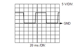 Fuel Lid Operation Signal for Combination Meter Assembly
 | ECM Terminal Name | Between LSTM and E1 |
| Tester Range | 5 V/DIV., 20 ms./DIV. |
| Condition | Multi-information display displaying "Close Fuel Lid" |
WAVEFORM 7
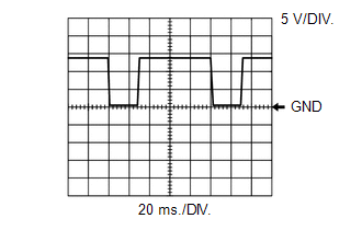 Fuel Lid Operation Signal for Combination Meter Assembly
 | ECM Terminal Name | Between LSTM and E1 |
| Tester Range | 5 V/DIV., 20 ms./DIV. |
| Condition | Multi-information display displaying "Ready to Refuel" |
WAVEFORM 8
.png) Throttle Actuator Operation Signal (Negative Terminal)
Throttle Actuator Operation Signal (Negative Terminal) | ECM Terminal Name | Between M- and E1 |
| Tester Range | 5 V/DIV., 1 ms./DIV. |
| Condition | Idling with warm engine |
HINT:
The duty ratio varies depending on the throttle actuator operation.
WAVEFORM 9
.png) Throttle Actuator Operation Signal (Positive Terminal)
Throttle Actuator Operation Signal (Positive Terminal) | ECM Terminal Name | Between M+ and E1 |
| Tester Range | 5 V/DIV., 1 ms./DIV. |
| Condition | Idling with warm engine |
HINT:
The duty ratio varies depending on the throttle actuator operation.
WAVEFORM 10
.png) EGR Valve Assembly Operation Signal
EGR Valve Assembly Operation Signal | ECM Terminal Name | CH1: Between EGA+ and E1 CH2: Between EGA- and E1 |
| CH1: Between EGB+ and E1 CH2: Between EGB- and E1 | |
| Tester Range | 5 V/DIV., 5 μs./DIV. |
| Condition | Idling with warm engine |
HINT:
When the EGR valve assembly is operating, a waveform is produced at each terminal.
WAVEFORM 11
.png) Air Fuel Ratio Sensor (Sensor 2) Heater Operation Signal
Air Fuel Ratio Sensor (Sensor 2) Heater Operation Signal | ECM Terminal Name | Between HA1B and E1 |
| Tester Range | 5 V/DIV., 10 ms./DIV. |
| Condition | Idling with cold engine |
WAVEFORM 12
Air Fuel Ratio Sensor (Sensor 1) Heater Operation Signal | ECM Terminal Name | Between HA1A and E1 |
| Tester Range | 5 V/DIV., 10 ms./DIV. |
| Condition | Idling with cold engine |
WAVEFORM 13
.png) No. 1 (to No. 4) Direct Fuel Injector Assembly Signal
No. 1 (to No. 4) Direct Fuel Injector Assembly Signal | ECM Terminal Name | CH1: Between #1D+ and E1 CH2: Between #1D- and E1 |
| CH1: Between #2D+ and E1 CH2: Between #2D- and E1 | |
| CH1: Between #3D+ and E1 CH2: Between #3D- and E1 | |
| CH1: Between #4D+ and E1 CH2: Between #4D- and E1 | |
| Tester Range | 50 V/DIV., 200 μs./DIV. |
| Condition | Idling with warm engine, Data List item "Injection Mode" displaying "Direct" |
WAVEFORM 14
.png) Fuel Pump Assembly (for High Pressure Side) Signal
Fuel Pump Assembly (for High Pressure Side) Signal | ECM Terminal Name | CH1: Between FP1+ and E1 CH2: Between FP1- and E1 |
| Tester Range | 20 V/DIV., 500 μs./DIV. |
| Condition | Idling with warm engine, Data List item "Injection Mode" displaying "Direct" |
WAVEFORM 15
.png) Oil Pressure Control Valve Operation Signal
Oil Pressure Control Valve Operation Signal | ECM Terminal Name | CH1: Between VOP+ and E1 CH2: Between VOP- and E1 |
| Tester Range | 5 V/DIV., 20 ms./DIV. |
| Condition | Idling with warm engine |
WAVEFORM 16
.png) Cam Timing Oil Control Solenoid Assembly Operation Signal
Cam Timing Oil Control Solenoid Assembly Operation Signal | ECM Terminal Name | Between OE1+ and OE1- |
| Tester Range | 5 V/DIV., 1 ms./DIV. |
| Condition | Idling |
WAVEFORM 17
Cam Timing Control Motor with EDU Assembly Signal (EDT Signal)| ECM Terminal Name | Between EDT1 and E1 |
| Tester Range | 1 V/DIV., 5 ms./DIV. |
| Condition | Idling with warm engine |
.png)
WAVEFORM 18
.png) Ignition Coil Assembly Signal (IGT Signal)
Ignition Coil Assembly Signal (IGT Signal) | ECM Terminal Name | Between IGT (1 to 4) and E1 |
| Tester Range | 5 V/DIV., 20 ms./DIV. |
| Condition | Idling with warm engine |
HINT:
The wavelength becomes shorter as the engine speed increases.
WAVEFORM 19
.png) Water Inlet Housing with Water Pump Sub-assembly Signal (from ECM to Water Inlet Housing with Water Pump Sub-assembly)
Water Inlet Housing with Water Pump Sub-assembly Signal (from ECM to Water Inlet Housing with Water Pump Sub-assembly) | ECM Terminal Name | Between WPO and E1 |
| Tester Range | 5 V/DIV., 20 ms./DIV. |
| Condition | Idling with warm engine |
HINT:
The duty ratio varies depending on the water inlet housing with water pump sub-assembly speed.
WAVEFORM 20
Water Inlet Housing with Water Pump Sub-assembly Signal (from Water Inlet Housing with Water Pump Sub-assembly to ECM) | ECM Terminal Name | Between WPI and E1 |
| Tester Range | 5 V/DIV., 20 ms./DIV. |
| Condition | Idling with warm engine |
HINT:
The wavelength becomes shorter as the water inlet housing with water pump sub-assembly speed increases.
WAVEFORM 21
.png) Purge VSV Operation Signal
Purge VSV Operation Signal | ECM Terminal Name | Between PRG and E1 |
| Tester Range | 10 V/DIV., 20 ms./DIV. |
| Condition | Idling with warm engine, under purge control |
HINT:
If the waveform is not similar to the illustration, check the waveform again after idling for 10 minutes or more.
WAVEFORM 22
Cam Timing Control Motor with EDU Assembly Signal (EMR Signal)| ECM Terminal Name | Between EMR1 and E1 |
| Tester Range | 2 V/DIV., 5 ms./DIV. |
| Condition | Idling with warm engine |
HINT:
The wavelength becomes shorter as the engine speed increases.
.png)
WAVEFORM 23
Cam Timing Control Motor with EDU Assembly Signal (EMD Signal)| ECM Terminal Name | Between EMD1 and E1 |
| Tester Range | 2 V/DIV., 100 ms./DIV. |
| Condition | Idling with warm engine |
.png)
WAVEFORM 24
.png) No. 1 (to No. 4) Port Fuel Injector Assembly Signal
No. 1 (to No. 4) Port Fuel Injector Assembly Signal | ECM Terminal Name | Between #10 (to #40) and E1 |
| Tester Range | 20 V/DIV., 20 ms./DIV. |
| Condition | Idling with warm engine (Data List item "Injection Mode" displaying "Port") |
HINT:
- The wavelength becomes shorter as the engine speed increases.
- When the port injection injectors are operating, Port is displayed for Injection Mode of the Data List.
WAVEFORM 25
.png) Camshaft Position Sensor Signal
Camshaft Position Sensor Signal | ECM Terminal Name | CH1: Between VV1+ and VV1- CH2: Between EV1+ and EV1- |
| Tester Range | 5 V/DIV., 20 ms./DIV. |
| Condition | Idling with warm engine |
HINT:
The wavelength becomes shorter as the engine speed increases.
WAVEFORM 26
.png) Crankshaft Position Sensor Signal
Crankshaft Position Sensor Signal | ECM Terminal Name | Between NE+ and NE- |
| Tester Range | 2 V/DIV., 20 ms./DIV. |
| Condition | Idling with warm engine |
HINT:
The wavelength becomes shorter as the engine speed increases.
WAVEFORM 27
.png) Mass Air Flow Meter Sub-assembly Signal
Mass Air Flow Meter Sub-assembly Signal | ECM Terminal Name | Between VG and E2G |
| Tester Range | 1 V/DIV., 100 μs./DIV. |
| Condition | Power switch on (IG) |
WAVEFORM 28
.png) Knock Control Sensor Signal
Knock Control Sensor Signal | ECM Terminal Name | Between KNK1 and EKNK |
| Tester Range | 1 V/DIV., 1 ms./DIV. |
| Condition | Engine speed maintained at 2500 rpm after warming up engine |
HINT:
- The wavelength becomes shorter as the engine speed increases.
- The waveforms and amplitudes displayed differ slightly depending on the vehicle.
READ NEXT:
 Diagnosis System
DIAGNOSIS SYSTEM DESCRIPTION When troubleshooting OBD II (On-Board Diagnostics) vehicles, the Techstream (complying with SAE J1978) must be connected to the DLC3 (Data Link Connector 3) of the vehicl
Dtc Check / Clear
DTC CHECK / CLEAR NOTICE: When the diagnosis system is changed from normal mode to check mode or vice versa, all DTCs and Freeze Frame Data recorded in normal mode are cleared. Before changing modes,
Freeze Frame Data
FREEZE FRAME DATA DESCRIPTION The ECM records vehicle and driving condition information as Freeze Frame Data the moment a DTC is stored. When troubleshooting, Freeze Frame Data can be helpful in deter
SEE MORE:
Dtc Check / Clear
DTC CHECK / CLEAR CHECK DTC (CHECK USING TECHSTREAM) (a) Connect the Techstream to the DLC3. (b) Turn the power switch on (IG) and wait for 90 seconds. (c) Turn the Techstream on. (d) Enter the following menus: Body Electrical / Navigation System / Trouble Codes. Body Electrical > Navigation Syst
Stop Light Control Relay Malfunction (C1380)
DESCRIPTION When any of the following conditions are met, the skid control ECU (brake booster with master cylinder assembly) sets the drive output (STPO) ON which operates the stop light control relay (stop light switch assembly) and turns on the stop lights. Illumination Conditions:
Pre-collisio
