Lexus ES: Stop Light Control Relay Malfunction (C1380)
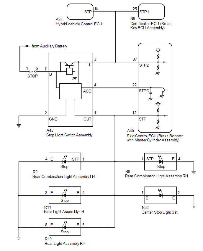
DESCRIPTION
When any of the following conditions are met, the skid control ECU (brake booster with master cylinder assembly) sets the drive output (STPO) ON which operates the stop light control relay (stop light switch assembly) and turns on the stop lights.
- Pre-collision brake is operating.
- The dynamic radar cruise control system is operating and is applying the brakes.
- Secondary collision brake is operating.
- Brake hold is operating.
- The parking brake is engaged while the vehicle is being driven.
| DTC No. | Detection Item | INF Code | DTC Detection Condition | Trouble Area | MIL | Note |
|---|---|---|---|---|---|---|
| C1380 | Stop Light Control Relay Malfunction | 761 762 |
|
| Does not come on | VSC DTC |
WIRING DIAGRAM
CAUTION / NOTICE / HINT
NOTICE:
-
After replacing the skid control ECU (brake booster with master cylinder assembly), perform linear solenoid valve offset learning, ABS holding solenoid valve learning, yaw rate and acceleration sensor zero point calibration and system information memorization after performing "Reset Memory".
Click here
.gif)
- Inspect the fuses for circuits related to this system before performing the following procedure.
PROCEDURE
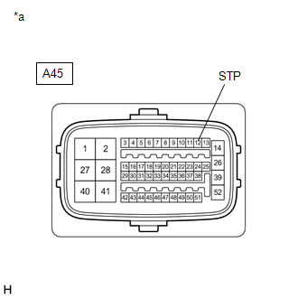
| 1. | CHECK HARNESS AND CONNECTOR (STP, STPO AND STP2 TERMINAL) |
| (a) Make sure that there is no looseness at the locking part and the connecting part of the connector. OK: The connector is securely connected. |
|
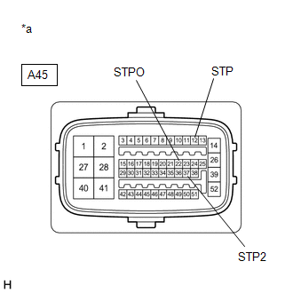
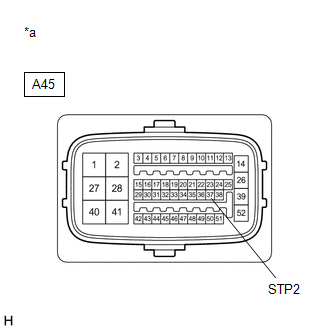
(b) Disconnect the A45 skid control ECU (brake booster with master cylinder assembly) connector.
(c) Check both the connector case and the terminals for deformation and corrosion.
OK:
No deformation or corrosion.
(d) Measure the voltage according to the value(s) in the table below.
Standard Voltage:
| Tester Connection | Condition | Specified Condition |
|---|---|---|
| A45-12 (STP) - Body ground | Stop light switch assembly on (Brake pedal depressed) | 11 to 14 V |
| A45-12 (STP) - Body ground | Stop light switch assembly off (Brake pedal released) | 1.5 V or less |
| A45-22 (STPO) - Body ground | Always | 11 to 14 V |
| A45-37 (STP2) - Body ground | Stop light switch assembly on (Brake pedal depressed) | 11 to 14 V |
| A45-37 (STP2) - Body ground | Stop light switch assembly off (Brake pedal released) | 1.5 V or less |
| Result | Proceed to |
|---|---|
| All terminal voltages are normal. | A |
| Only STP2 terminal voltage abnormal. | B |
| Only STPO terminal voltage abnormal. | C |
| Only STP terminal voltage abnormal. | D |
| STPO terminal and STP terminal voltage abnormal. | E |
| B |  | GO TO STEP 5 |
| C | | GO TO STEP 9 |
| D | | GO TO STEP 10 |
| E | | GO TO STEP 17 |
|

| 2. | PERFORM ACTIVE TEST USING TECHSTREAM (STOP LIGHT RELAY) |
(a) Reconnect the A45 skid control ECU (brake booster with master cylinder assembly) connector.
(b) Select the Active Test on the Techstream.
Click here
| Tester Display | Measurement Item | Control Range | Diagnostic Note |
|---|---|---|---|
| Stop Light Relay | Stop light control relay (Stop light switch assembly) | Relay ON/OFF | - |
| Tester Display |
|---|
| Stop Light Relay |
(c) According to the display on the Techstream, perform the Active Test and check the operation of the stop lights.
OK:
Stop lights turn on/off in accordance with the Active Test.
| NG | | GO TO STEP 4 |
|
| 3. | RECONFIRM DTC |
(a) Clear the DTCs.
Click here
(b) Select the Active Test on the Techstream.
Click here
| Tester Display | Measurement Item | Control Range | Diagnostic Note |
|---|---|---|---|
| Stop Light Relay | Stop light control relay (Stop light switch assembly) | Relay ON/OFF | - |
| Tester Display |
|---|
| Stop Light Relay |
(c) According to the display on the Techstream, perform the Active Test.
(d) Check if the same DTC is output.
Click here
| Result | Proceed to |
|---|---|
| DTC C1380 is output. | A |
| DTC C1380 is not output. | B |
| A | | REPLACE BRAKE BOOSTER WITH MASTER CYLINDER ASSEMBLY |
| B | | USE SIMULATION METHOD TO CHECK |
| 4. | INSPECT BRAKE BOOSTER WITH MASTER CYLINDER ASSEMBLY |
(a) Select the Active Test on the Techstream.
Click here
| Tester Display | Measurement Item | Control Range | Diagnostic Note |
|---|---|---|---|
| Stop Light Relay | Stop light control relay (Stop light switch assembly) | Relay ON/OFF | - |
| Tester Display |
|---|
| Stop Light Relay |
| (b) Measure the voltage according to the value(s) in the table below. Standard Voltage:
|
|
| OK | | REPLACE STOP LIGHT SWITCH ASSEMBLY |
| NG | | REPLACE BRAKE BOOSTER WITH MASTER CYLINDER ASSEMBLY |
| 5. | CHECK HARNESS AND CONNECTOR (BRAKE BOOSTER WITH MASTER CYLINDER ASSEMBLY - HYBRID VEHICLE CONTROL ECU) |
| (a) Make sure that there is no looseness at the locking part and the connecting part of the connector. OK: The connector is securely connected. |
|
(b) Disconnect the A32 hybrid vehicle control ECU connector.
(c) Check both the connector case and the terminals for deformation and corrosion.
OK:
No deformation or corrosion.
(d) Measure the voltage according to the value(s) in the table below.
Standard Voltage:
| Tester Connection | Condition | Specified Condition |
|---|---|---|
| A45-37 (STP2) - Body ground | Stop light switch assembly on (Brake pedal depressed) | 11 to 14 V |
| A45-37 (STP2) - Body ground | Stop light switch assembly off (Brake pedal released) | 1.5 V or less |
| OK | | REPLACE HYBRID VEHICLE CONTROL ECU |
|
| 6. | CHECK HARNESS AND CONNECTOR (BRAKE BOOSTER WITH MASTER CYLINDER ASSEMBLY - SMART KEY ECU ASSEMBLY) |
| (a) Make sure that there is no looseness at the locking part and the connecting part of the connector. OK: The connector is securely connected. |
|
(b) Disconnect the N9 certification ECU (smart key ECU assembly) connector.
(c) Check both the connector case and the terminals for deformation and corrosion.
OK:
No deformation or corrosion.
(d) Measure the voltage according to the value(s) in the table below.
Standard Voltage:
| Tester Connection | Condition | Specified Condition |
|---|---|---|
| A45-37 (STP2) - Body ground | Stop light switch assembly on (Brake pedal depressed) | 11 to 14 V |
| A45-37 (STP2) - Body ground | Stop light switch assembly off (Brake pedal released) | 1.5 V or less |
| OK | | REPLACE SMART KEY ECU ASSEMBLY |
|
| 7. | CHECK HARNESS AND CONNECTOR (BRAKE BOOSTER WITH MASTER CYLINDER ASSEMBLY - STOP LIGHT SWITCH ASSEMBLY) |
| (a) Make sure that there is no looseness at the locking part and the connecting part of the connector. OK: The connector is securely connected. |
|
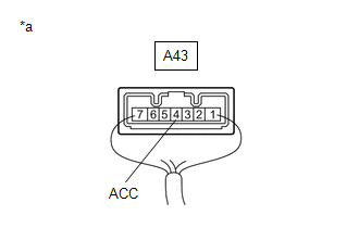
(b) Disconnect the A43 stop light switch assembly connector.
(c) Check both the connector case and the terminals for deformation and corrosion.
OK:
No deformation or corrosion.
(d) Measure the voltage according to the value(s) in the table below.
Standard Voltage:
| Tester Connection | Condition | Specified Condition |
|---|---|---|
| A45-37 (STP2) - Body ground | Always | 1.5 V or less |
| NG | | REPAIR OR REPLACE HARNESS OR CONNECTOR |
|
| 8. | CHECK HARNESS AND CONNECTOR (BRAKE BOOSTER WITH MASTER CYLINDER ASSEMBLY - STOP LIGHT SWITCH ASSEMBLY) |
(a) Measure the resistance according to the value(s) in the table below.
Standard Resistance:
| Tester Connection | Condition | Specified Condition |
|---|---|---|
| A45-37 (STP2) - A43-3 (L) | Always | Below 1 Ω |
| A45-37 (STP2) or A43-3 (L) - Body ground | Always | 10 kΩ or higher |
| OK | | REPLACE STOP LIGHT SWITCH ASSEMBLY |
| NG | | REPAIR OR REPLACE HARNESS OR CONNECTOR |
| 9. | CHECK HARNESS AND CONNECTOR (BRAKE BOOSTER WITH MASTER CYLINDER ASSEMBLY - STOP LIGHT SWITCH ASSEMBLY) |
(a) Make sure that there is no looseness at the locking part and the connecting part of the connector.
OK:
The connector is securely connected.
(b) Disconnect the A43 stop light switch assembly connector.
(c) Check both the connector case and the terminals for deformation and corrosion.
OK:
No deformation or corrosion.
(d) Measure the resistance according to the value(s) in the table below.
Standard Resistance:
| Tester Connection | Condition | Specified Condition |
|---|---|---|
| A45-22 (STPO) - A43-4 (ACC) | Always | Below 1 Ω |
| OK | | REPLACE STOP LIGHT SWITCH ASSEMBLY |
| NG | | REPAIR OR REPLACE HARNESS OR CONNECTOR |
| 10. | CHECK HARNESS AND CONNECTOR (BRAKE BOOSTER WITH MASTER CYLINDER ASSEMBLY - REAR COMBINATION LIGHT ASSEMBLY LH) |
| (a) Make sure that there is no looseness at the locking part and the connecting part of the connector. OK: The connector is securely connected. |
|
(b) Disconnect the R9 rear combination light assembly LH connector.
(c) Check both the connector case and the terminals for deformation and corrosion.
OK:
No deformation or corrosion.
(d) Measure the voltage according to the value(s) in the table below.
Standard Voltage:
| Tester Connection | Condition | Specified Condition |
|---|---|---|
| A45-12 (STP) - Body ground | Stop light switch assembly on (Brake pedal depressed) | 11 to 14 V |
| A45-12 (STP) - Body ground | Stop light switch assembly off (Brake pedal released) | 1.5 V or less |
| OK | | REPLACE REAR COMBINATION LIGHT ASSEMBLY LH |
|
| 11. | CHECK HARNESS AND CONNECTOR (BRAKE BOOSTER WITH MASTER CYLINDER ASSEMBLY - REAR COMBINATION LIGHT ASSEMBLY RH) |
| (a) Make sure that there is no looseness at the locking part and the connecting part of the connector. OK: The connector is securely connected. |
|
(b) Disconnect the R8 rear combination light assembly RH connector.
(c) Check both the connector case and the terminals for deformation and corrosion.
OK:
No deformation or corrosion.
(d) Measure the voltage according to the value(s) in the table below.
Standard Voltage:
| Tester Connection | Condition | Specified Condition |
|---|---|---|
| A45-12 (STP) - Body ground | Stop light switch assembly on (Brake pedal depressed) | 11 to 14 V |
| A45-12 (STP) - Body ground | Stop light switch assembly off (Brake pedal released) | 1.5 V or less |
| OK | | REPLACE REAR COMBINATION LIGHT ASSEMBLY RH |
|
| 12. | CHECK HARNESS AND CONNECTOR (BRAKE BOOSTER WITH MASTER CYLINDER ASSEMBLY - REAR LIGHT ASSEMBLY LH) |
| (a) Make sure that there is no looseness at the locking part and the connecting part of the connector. OK: The connector is securely connected. |
|
(b) Disconnect the R11 rear light assembly LH connector.
(c) Check both the connector case and the terminals for deformation and corrosion.
OK:
No deformation or corrosion.
(d) Measure the voltage according to the value(s) in the table below.
Standard Voltage:
| Tester Connection | Condition | Specified Condition |
|---|---|---|
| A45-12 (STP) - Body ground | Stop light switch assembly on (Brake pedal depressed) | 11 to 14 V |
| A45-12 (STP) - Body ground | Stop light switch assembly off (Brake pedal released) | 1.5 V or less |
| OK | | REPLACE REAR LIGHT ASSEMBLY LH |
|
| 13. | CHECK HARNESS AND CONNECTOR (BRAKE BOOSTER WITH MASTER CYLINDER ASSEMBLY - REAR LIGHT ASSEMBLY RH) |
| (a) Make sure that there is no looseness at the locking part and the connecting part of the connector. OK: The connector is securely connected. |
|
(b) Disconnect the R10 rear light assembly RH connector.
(c) Check both the connector case and the terminals for deformation and corrosion.
OK:
No deformation or corrosion.
(d) Measure the voltage according to the value(s) in the table below.
Standard Voltage:
| Tester Connection | Condition | Specified Condition |
|---|---|---|
| A45-12 (STP) - Body ground | Stop light switch assembly on (Brake pedal depressed) | 11 to 14 V |
| A45-12 (STP) - Body ground | Stop light switch assembly off (Brake pedal released) | 1.5 V or less |
| OK | | REPLACE REAR LIGHT ASSEMBLY RH |
|
| 14. | CHECK HARNESS AND CONNECTOR (BRAKE BOOSTER WITH MASTER CYLINDER ASSEMBLY - CENTER STOP LIGHT SET) |
| (a) Make sure that there is no looseness at the locking part and the connecting part of the connector. OK: The connector is securely connected. |
|
(b) Disconnect the N52 center stop light set connector.
(c) Check both the connector case and the terminals for deformation and corrosion.
OK:
No deformation or corrosion.
(d) Measure the voltage according to the value(s) in the table below.
Standard Voltage:
| Tester Connection | Condition | Specified Condition |
|---|---|---|
| A45-12 (STP) - Body ground | Stop light switch assembly on (Brake pedal depressed) | 11 to 14 V |
| A45-12 (STP) - Body ground | Stop light switch assembly off (Brake pedal released) | 1.5 V or less |
| OK | | REPLACE CENTER STOP LIGHT SET |
|
| 15. | CHECK HARNESS AND CONNECTOR (BRAKE BOOSTER WITH MASTER CYLINDER ASSEMBLY - STOP LIGHT SWITCH ASSEMBLY) |
| (a) Make sure that there is no looseness at the locking part and the connecting part of the connector. OK: The connector is securely connected. |
|
(b) Disconnect the A43 stop light switch assembly connector.
(c) Check both the connector case and the terminals for deformation and corrosion.
OK:
No deformation or corrosion.
(d) Measure the voltage according to the value(s) in the table below.
Standard Voltage:
| Tester Connection | Condition | Specified Condition |
|---|---|---|
| A45-12 (STP) - Body ground | Always | 1.5 V or less |
| NG | | REPAIR OR REPLACE HARNESS OR CONNECTOR |
|
| 16. | CHECK HARNESS AND CONNECTOR (BRAKE BOOSTER WITH MASTER CYLINDER ASSEMBLY - STOP LIGHT SWITCH ASSEMBLY) |
(a) Measure the resistance according to the value(s) in the table below.
Standard Resistance:
| Tester Connection | Condition | Specified Condition |
|---|---|---|
| A43-1 (OUT) - A45-12 (STP) | Always | Below 1 Ω |
| A43-1 (OUT) or A45-12 (STP) - Body ground | Always | 10 kΩ or higher |
| OK | | REPLACE STOP LIGHT SWITCH ASSEMBLY |
| NG | | REPAIR OR REPLACE HARNESS OR CONNECTOR |
| 17. | CHECK STOP LIGHT SWITCH ASSEMBLY POWER SOURCE CIRCUIT |
| (a) Make sure that there is no looseness at the locking part and the connecting part of the connector. OK: The connector is securely connected. |
|
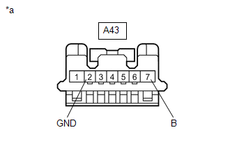
(b) Disconnect the A43 stop light switch assembly connector.
(c) Check both the connector case and the terminals for deformation and corrosion.
OK:
No deformation or corrosion.
(d) Measure the voltage according to the value(s) in the table below.
Standard Voltage:
| Tester Connection | Condition | Specified Condition |
|---|---|---|
| A43-7 (B) - Body ground | Always | 11 to 14 V |
(e) Measure the resistance according to the value(s) in the table below.
Standard Resistance:
| Tester Connection | Condition | Specified Condition |
|---|---|---|
| A43-2 (GND) - Body ground | Always | Below 1 Ω |
| NG | | REPAIR OR REPLACE HARNESS OR CONNECTOR |
|
| 18. | CHECK HARNESS AND CONNECTOR (BRAKE BOOSTER WITH MASTER CYLINDER ASSEMBLY - STOP LIGHT SWITCH ASSEMBLY) |
(a) Measure the resistance according to the value(s) in the table below.
Standard Resistance:
| Tester Connection | Condition | Specified Condition |
|---|---|---|
| A45-22 (STPO) or A43-4 (ACC) - Body ground | Always | 10 kΩ or higher |
| OK | | REPLACE STOP LIGHT SWITCH ASSEMBLY |
| NG | | REPAIR OR REPLACE HARNESS OR CONNECTOR |
READ NEXT:
 Stop Light Control Relay Malfunction (C1380)
DESCRIPTION When any of the following conditions are met, the skid control ECU (brake booster with master cylinder assembly) sets the drive output (STPO) ON which operates the stop light control relay
Abnormal Power Supply Voltage in Yaw Rate and/or Deceleration Sensor (C1381)
DESCRIPTION The airbag ECU assembly has a built-in yaw rate and acceleration sensor and detects the vehicle condition using 2 circuits (GL1, GL2). If a power source malfunction signal from the yaw rat
Abnormal Leak in Accumulator (C1391)
DESCRIPTION This DTC is stored if internal or external brake fluid leaks are detected due to improper sealing in the brake actuator (brake booster with master cylinder assembly) or brake booster pump
SEE MORE:
Problem Symptoms Table
PROBLEM SYMPTOMS TABLE NOTICE:
If the battery voltage becomes low, battery load control will operate in order to ensure sufficient power is supplied to the power steering system. In this case, the windshield deicer system may not operate.
HINT:
Use the table below to help determine the caus
Operation Check
OPERATION CHECK CHECK WINDOW DEFOGGER SYSTEM (a) Turn the engine switch on (IG). (b) Check that the rear window defogger wire becomes warm by operating the rear window defogger switch of the air conditioning control assembly. (c) When the vehicle is stopped, confirm that the window defogger system o
