Lexus ES: System Diagram
SYSTEM DIAGRAM
 Communication Table
 | Transmitting ECU | Receiving ECU | Signal | Communication Method |
|---|---|---|---|
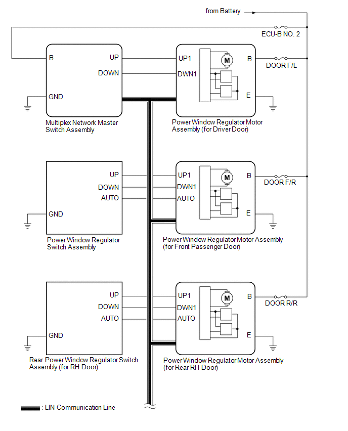
| Multiplex Network Master Switch Assembly | Power Window Regulator Motor Assembly (for Driver Door) | Power window auto up and down signal | LIN |
| Power window remote up and down signal | LIN | |
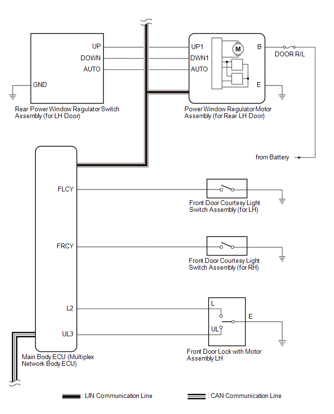
| Main Body ECU (Multiplex Network Body ECU) |
| Power window operation permission signal | LIN |
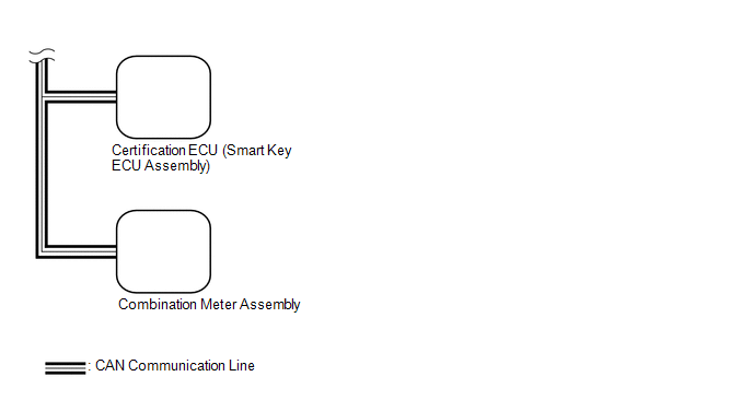
| Certification ECU (Smart Key ECU Assembly) | Main Body ECU (Multiplex Network Body ECU) | Wireless power window operation signal | CAN |
| Main Body ECU (Multiplex Network Body ECU) | Combination Meter Assembly | Window open warning request signal | CAN |
READ NEXT:
 System Description
SYSTEM DESCRIPTION POWER WINDOW CONTROL SYSTEM DESCRIPTION (a) The power window control system controls the power window operation using the power window regulator motor assemblies. The main controls
How To Proceed With Troubleshooting
CAUTION / NOTICE / HINT HINT:
Use the following procedure to troubleshoot the power window control system.
*: Use the Techstream.
PROCEDURE 1. VEHICLE BROUGHT TO WORKSHOP
NEXT
Operation Check
OPERATION CHECK CHECK WINDOW LOCK FUNCTION HINT: Before performing the window lock switch operation check, make sure that the window lock switch is off (the switch is not pushed in). (a) Turn the win
SEE MORE:
Hybrid/EV Battery Stack 1 Circuit Resistance Out of Range (P33DA1E,P33DB1E)
DESCRIPTION The HV battery is composed of 70 cells (3.7 V each) in series. The battery ECU assembly monitors the internal resistance of each HV battery cell to detect malfunctions of the HV battery. DTC No. Detection Item DTC Detection Condition Trouble Area MIL Warning Indicate P33
Freeze Frame Data
FREEZE FRAME DATA DESCRIPTION (a) Whenever a road sign assist system DTC is stored, the forward recognition camera stores the current vehicle state (ECU and sensor information) as Freeze Frame Data. CHECK FREEZE FRAME DATA (a) Connect the Techstream to the DLC3. (b) Turn the engine switch on (IG). (
© 2016-2026 Copyright www.lexguide.net
