Lexus ES: Operation Check
OPERATION CHECK
CHECK WINDOW LOCK FUNCTION
HINT:
Before performing the window lock switch operation check, make sure that the window lock switch is off (the switch is not pushed in).
(a) Turn the window lock switch of the multiplex network master switch assembly on (pushed in) and check that the front passenger and rear windows are disabled.
OK:
Front passenger and rear windows are disabled.
(b) Turn the window lock switch off (not pushed in) and check that the front passenger and rear windows can be operated normally.
OK:
Front passenger and rear windows operate normally.
CHECK MANUAL UP / DOWN FUNCTION
(a) Check that the driver door power window operates as follows:
OK| Condition | Master Switch | Switch Operation | Power Window |
|---|---|---|---|
| Engine switch on (IG) | Driver door | Pulled halfway up | UP (Closes) |
| Pushed halfway down | DOWN (Opens) |
(b) Check that the front passenger door power window and rear door power windows operate as follows:
OK| Condition | Regulator Switch | Switch Operation | Power Window |
|---|---|---|---|
| Front passenger door | Pulled halfway up | UP (Closes) |
| Pushed halfway down | DOWN (Opens) | ||
| Rear LH door | Pulled halfway up | UP (Closes) | |
| Pushed halfway down | DOWN (Opens) | ||
| Rear RH door | Pulled halfway up | UP (Closes) | |
| Pushed halfway down | DOWN (Opens) |
CHECK AUTO UP / DOWN FUNCTION
(a) Check that the driver door power window operates as follows:
OK| Condition | Master Switch | Switch Operation | Power Window |
|---|---|---|---|
| Engine switch on (IG) | Driver door | Pulled up (One touch operation) | AUTO UP (Closes) |
| Pushed down (One touch operation) | AUTO DOWN (Opens) |
(b) Check that the front passenger door power window and rear door power windows operate as follows:
OK| Condition | Regulator Switch | Switch Operation | Power Window |
|---|---|---|---|
| Front passenger door | Pulled up (One touch operation) | AUTO UP (Closes) |
| Pushed down (One touch operation) | AUTO DOWN (Opens) | ||
| Rear LH door | Pulled up (One touch operation) | AUTO UP (Closes) | |
| Pushed down (One touch operation) | AUTO DOWN (Opens) | ||
| Rear RH door | Pulled up (One touch operation) | AUTO UP (Closes) | |
| Pushed down (One touch operation) | AUTO DOWN (Opens) |
CHECK REMOTE MANUAL UP / DOWN FUNCTION
(a) Check that the front passenger door power window and rear door power windows operate as follows:
OK| Condition | Master Switch | Switch Operation | Power Window |
|---|---|---|---|
| Front passenger door | Pulled halfway up | UP (Closes) |
| Pushed halfway down | DOWN (Opens) | ||
| Rear LH door | Pulled halfway up | UP (Closes) | |
| Pushed halfway down | DOWN (Opens) | ||
| Rear RH door | Pulled halfway up | UP (Closes) | |
| Pushed halfway down | DOWN (Opens) |
CHECK REMOTE AUTO UP / DOWN FUNCTION
(a) Check that the front passenger door power window and rear door power windows operate as follows:
OK| Condition | Master Switch | Switch Operation | Power Window |
|---|---|---|---|
| Front passenger door | Pulled up (One touch operation) | AUTO UP (Closes) |
| Pushed down (One touch operation) | AUTO DOWN (Opens) | ||
| Rear LH door | Pulled up (One touch operation) | AUTO UP (Closes) | |
| Pushed down (One touch operation) | AUTO DOWN (Opens) | ||
| Rear RH door | Pulled up (One touch operation) | AUTO UP (Closes) | |
| Pushed down (One touch operation) | AUTO DOWN (Opens) |
CHECK KEY-OFF OPERATION FUNCTION
(a) Check that each power window can be operated with the multiplex network master switch assembly, power window regulator switch assembly or rear power window regulator switch assembly after the engine switch is turned off.
HINT:
If the window lock switch is on, the power windows cannot be operated using the power window regulator switch assembly and rear power window regulator switch assemblies. Therefore, turn the window lock switch off before checking the power window operation.
(b) Check that the key-off operation function does not operate immediately after the driver door or front passenger door is opened.
HINT:
- If a power window is being operated by auto operation while the key-off operation function is on, and the driver door or front passenger door is opened, the power window will stop operating.
(c) Check that all of the power windows cannot be operated after more than approximately 45 seconds have elapsed since the engine switch is turned off.
- *: This function is set through a customize setting, as it is off by default.
CHECK WIRELESS TRANSMITTER-LINKED FUNCTION*
(a) Check that all of the power windows operate as follows when operating the key:
OK| Condition | Transmitter Operation | Power Window |
|---|---|---|
| No key is inside vehicle, and all doors are closed and locked | UNLOCK switch pressed for more than 3 seconds | DOWN (Opens) |
| No key is inside vehicle, and all doors are closed and locked | UNLOCK switch released | STOP |
CHECK KEY-LINKED FUNCTION*
- *: This function is set through a customize setting, as it is off by default.
(a) Check that all of the power windows operate as follows:
OK| Condition | Door Key Cylinder Operation | Power Window |
|---|---|---|
| No key is inside vehicle, and all doors are closed | Turned to the lock position and held for more than 1.5 seconds | UP (Closes) |
| No Key is inside vehicle, and all doors are closed | Returned to neutral position | STOP |
| No Key is inside vehicle, and all doors are closed | Turned to the unlock position and held for more than 1.5 seconds | DOWN (Opens) |
| No Key is inside vehicle, and all doors are closed | Returned to neutral position | STOP |
CHECK WINDOW OPEN WARNING FUNCTION
(a) Open a window using the power window switch.
(b) Turn the engine switch from on (IG) to off, open the driver door with the Key in the vehicle and check that the warning buzzer in the combination meter assembly sounds once. Then, check that message is displayed on the multi-information display in the combination meter assembly.
CHECK JAM PROTECTION FUNCTION
(a) Check the basic function.
CAUTION:
Do not put your fingers between the door frame and door glass to check the jam protection function. Also, prevent any part of your body from being caught during inspection.
HINT:
The jam protection function is operative during both the auto up and manual up operations while the engine is started or the engine switch is on (IG), and also for approximately 45 seconds after the engine switch is turned off.
(1) Fully open the power window.
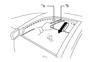
| *a | Check Jig |
| *b | Cloth |
(2) Set a check jig wrapped with a piece of cloth near the power window fully closed position.
(3) Operate the auto up or manual up function and check that the power window stops and goes down after the check jig is caught between the door glass and door frame, and stops.
HINT:
- If a manual up operation is performed from the seat, the door glass will lower approximately 30 mm (1.181 in.) from the point it contacts the end of the hammer or continue lowering for approximately 5 seconds and then stop.
- If a manual up operation is not performed from the seat, the door glass will lower approximately 125 mm (4.921 in.) from the point it contacts the end of the hammer or continue lowering for approximately 5 seconds and then stop.
- After the jam protection function operates when an auto up or manual up operation is performed, the jam protection function will not operate when the manual up operation is performed again within approximately 4 seconds.
- After the catch protection function has operated, the auto up function will not operate the first time the power window auto up switch is operated. The auto up function will operate normally after the first power window switch operation.
(4) While the power window is moving down, check that the door glass cannot be raised using the power window switch.
CHECK CATCH PROTECTION FUNCTION
(a) Check the basic function.
CAUTION:
Do not put your fingers between the door frame and door glass to check the jam protection function. Also, prevent any part of your body from being caught during inspection.
HINT:
The catch protection function is operative during both the auto down and manual down operations while the engine is started or the engine switch is on (IG), and also for approximately 45 seconds after the engine switch is turned off.
(1) Fully close all of the power windows.
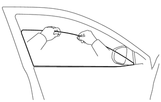
(2) Operate the auto down or manual down function to open the power window, grasp the upper edge of the door glass with one or two hands and check that the power window stops.
HINT:
After the catch protection function has operated when an auto down or manual down operation was performed, the catch protection function will not operate if the manual down operation is performed again within approximately 4 seconds.
CHECK POWER WINDOW SWITCH LED ILLUMINATION
(a) Check the LED illumination (multiplex network master switch assembly).
(1) Check that the LEDs located in the multiplex network master switch assembly illuminate when the headlight dimmer switch is in the tail position.
(b) Check the LED illumination (power window regulator switch assembly).
(1) Check that the LED located in the power window regulator switch assembly illuminates when the headlight dimmer switch is in the tail position.
(c) Check the LED illumination (rear power window regulator switch assembly).
(1) Check that the LED located in each rear power window regulator switch assembly illuminates when the headlight dimmer switch is in the tail position.
READ NEXT:
 Customize Parameters
CUSTOMIZE PARAMETERS CUSTOMIZE POWER WINDOW CONTROL SYSTEM HINT: The following items can be customized. NOTICE:
When the customer requests a change in a function, first make sure that the function
Initialization
INITIALIZATION INITIALIZE POWER WINDOW CONTROL SYSTEM (ALL DOORS) NOTICE:
When any of the door window regulator sub-assemblies, power window regulator motor assemblies, door glass or door glass run
Problem Symptoms Table
PROBLEM SYMPTOMS TABLE HINT:
Use the table below to help determine the cause of problem symptoms. If multiple suspected areas are listed, the potential causes of the symptoms are listed in order of
SEE MORE:
Components
COMPONENTS ILLUSTRATION *1 REAR NO. 2 SUSPENSION ARM ASSEMBLY LH *2 REAR NO. 2 SUSPENSION ARM ASSEMBLY RH *3 REAR SUSPENSION MEMBER SUB-ASSEMBLY *4 REAR UPPER CONTROL ARM ASSEMBLY LH *5 REAR UPPER CONTROL ARM ASSEMBLY RH *6 REAR SUSPENSION MEMBER LOWER STOPPER *7
Parts Location
PARTS LOCATION ILLUSTRATION *1 GENERATOR ASSEMBLY *2 ECM *3 NO. 1 ENGINE ROOM RELAY BLOCK AND NO. 1 JUNCTION BLOCK ASSEMBLY - - ILLUSTRATION *1 COMBINATION METER ASSEMBLY - -
