Lexus ES: System Diagram
SYSTEM DIAGRAM
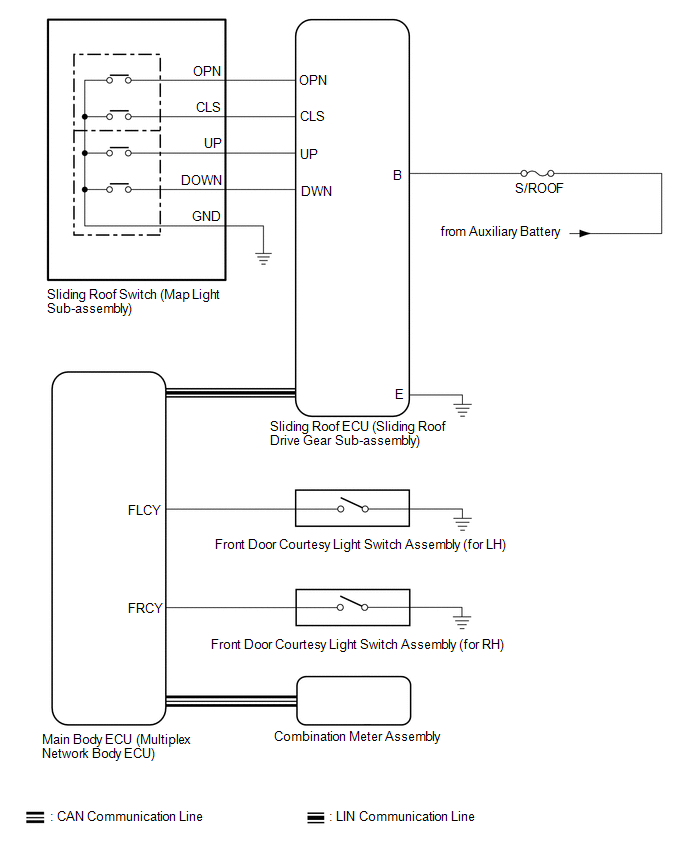 Communication Table
 | Sender | Receiver | Signal | Line |
|---|---|---|---|
| Main Body ECU (Multiplex Network Body ECU) | Sliding Roof ECU (Sliding Roof Drive Gear Sub-assembly) |
| LIN |
| Sliding Roof ECU (Sliding Roof Drive Gear Sub-assembly) | Main Body ECU (Multiplex Network Body ECU) | Sliding roof position signal | LIN |
| Combination Meter Assembly | Main Body ECU (Multiplex Network Body ECU) | Vehicle speed signal | CAN |
| Main Body ECU (Multiplex Network Body ECU) | Combination Meter Assembly | Sliding roof open warning request signal | CAN |
READ NEXT:
 System Description
SYSTEM DESCRIPTION SLIDING ROOF SYSTEM DESCRIPTION (a) The sliding roof system controls the sliding roof operation using the sliding roof ECU (sliding roof drive gear sub-assembly). Operating the slid
How To Proceed With Troubleshooting
CAUTION / NOTICE / HINT HINT:
Use the following procedure to troubleshoot the sliding roof system.
*: Use the Techstream.
PROCEDURE 1. VEHICLE BROUGHT TO WORKSHOP
NEXT
Operation Check
OPERATION CHECK CHECK AUTO OPERATION FUNCTION NOTICE:
Make sure that initialization has been completed before performing this inspection.
Click here
The sliding roof auto operation can be custo
SEE MORE:
Removal
REMOVAL
CAUTION / NOTICE / HINT
The necessary procedures (adjustment, calibration, initialization or registration)
that must be performed after parts are removed and installed, or replaced battery
removal/installation are shown below.
Necessary Procedures After Parts Removed/Installed/Replace
Power Retractable Mirrors do not Operate with Power Retract Mirror Switch
DESCRIPTION The outer mirror switch assembly sends the retractable outer mirror switch signal to the main body ECU (multiplex network body ECU). The main body ECU (multiplex network body ECU) then sends the mirror retract/return signal to each outer mirror control ECU assembly via CAN communication.
© 2016-2026 Copyright www.lexguide.net
