Lexus ES: System Diagram
Lexus ES (XZ10) Service Manual / Steering / Power Assist Systems / Power Steering System (for Hv Model) / System Diagram
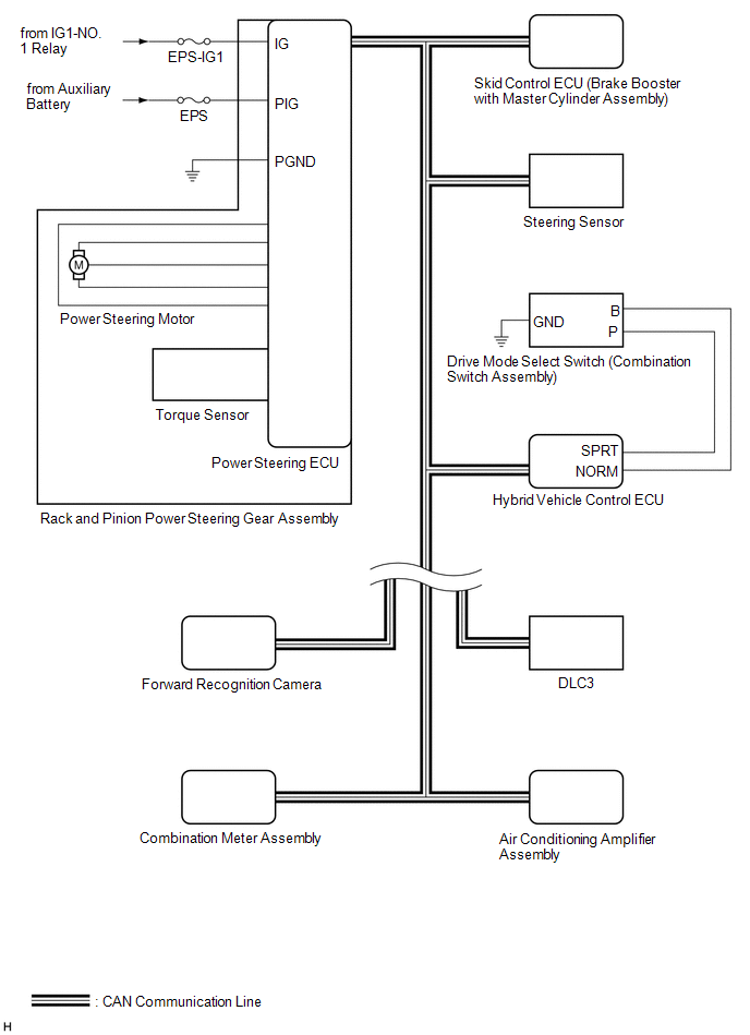
SYSTEM DIAGRAM
READ NEXT:
 System Description
SYSTEM DESCRIPTION DESCRIPTION (a) The power steering ECU (rack and pinion power steering gear assembly) generates the necessary steering assist torque by calculating the steering assist force and con
How To Proceed With Troubleshooting
CAUTION / NOTICE / HINT HINT:
Use the following procedure to troubleshoot the power steering system.
*: Use the Techstream.
PROCEDURE 1. VEHICLE BROUGHT TO WORKSHOP
NEXT
Calibration
CALIBRATION TORQUE SENSOR ZERO POINT CALIBRATION (USING TECHSTREAM) NOTICE: Perform torque sensor zero point calibration if any of the following conditions occur:
The rack and pinion power steering
SEE MORE:
Drive Motor "A" Temperature Sensor Circuit Short to Ground (P0A2A11,P0A2A15)
DTC SUMMARY MALFUNCTION DESCRIPTION These DTCs are stored when the motor temperature sensor output is abnormal. The cause of this malfunction may be one of the following: Hybrid vehicle control ECU malfunction
Hybrid vehicle control ECU internal malfunction
Motor temperature sensor malfunctio
Steering Pad Switch Circuit
DESCRIPTION This circuit sends an operation signal from the steering pad switch assembly to the radio receiver assembly. If there is an open in the circuit, the audio system cannot be operated using the steering pad switch assembly. If there is a short in the circuit, the same condition as when a sw
© 2016-2026 Copyright www.lexguide.net
