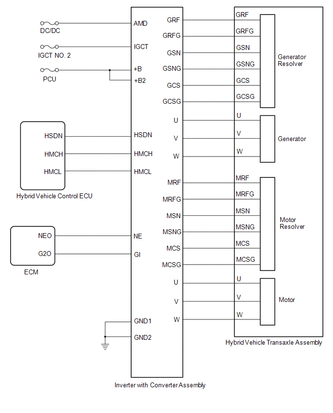
Lexus ES: System Diagram
SYSTEM DIAGRAM
READ NEXT:
 How To Proceed With Troubleshooting
CAUTION / NOTICE / HINT HINT:
*: Use the Techstream
Use the following procedure to troubleshoot the motor generator control system.
PROCEDURE 1. VEHICLE BROUGHT TO WORKSHOP
NEXT
Utility
UTILITY ALL READINESS HINT:
With "All Readiness", you can check whether or not the DTC judgment has been completed by using the Techstream.
Check "All Readiness" after simulating malfunction symp
Terminals Of Ecu
TERMINALS OF ECU *1 Inverter with Converter Assembly HINT: Since the inverter with converter assembly uses waterproof connectors, the voltage and waveforms cannot be inspected directly. Stand
SEE MORE:
Combination Switch
ComponentsCOMPONENTS ILLUSTRATION *1 EV DRIVE MODE SWITCH (NO. 3 COMBINATION SWITCH ASSEMBLY) - - InspectionINSPECTION PROCEDURE 1. INSPECT EV DRIVE MODE SWITCH (NO. 3 COMBINATION SWITCH ASSEMBLY) (a) Inspect EV mode switch (No. 2 combination switch assembly) (1) Measure the resist
On-vehicle Inspection
ON-VEHICLE INSPECTION PROCEDURE 1. INSPECT MASS AIR FLOW METER SUB-ASSEMBLY HINT: Perform "Inspection After Repair" after replacing the mass air flow meter sub-assembly. Click here (a) Read the value of Data List item "Mass Air Flow Sensor" using the Techstream. NOTICE: Perform the inspection of
© 2016-2026 Copyright www.lexguide.net
