Lexus ES: Extension Module Disconnected 2 (B1543)
DESCRIPTION
If the radio receiver assembly cannot detect the navigation ECU for a certain period of time (90 seconds) after the power switch is turned on (ACC) and the radio receiver assembly confirms that the information is missing by checking past navigation ECU recognition information (registered information), this DTC will be stored.
HINT:
The Navigation system uses USB communication between devices. If an open, short, short to +B or short to ground occurs in the USB circuit, communication is interrupted and the Navigation system will not operate normally.
| DTC No. | Detection Item | DTC Detection Condition | Trouble Area |
|---|---|---|---|
| B1543 | Extension Module Disconnected 2 | Navigation ECU disconnected |
|
HINT:
This DTC may be stored due to environmental reasons such as electrical noise or interference.
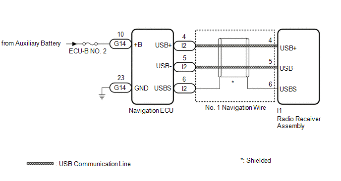
WIRING DIAGRAM
CAUTION / NOTICE / HINT
NOTICE:
-
Depending on the parts that are replaced during vehicle inspection or maintenance, performing initialization, registration or calibration may be needed. Refer to Precaution for Navigation System.
Click here
.gif)
-
When replacing the radio receiver assembly or navigation ECU, always replace it with a new one. If a radio receiver assembly or navigation ECU which was installed to another vehicle is used, the following may occur:
- A communication malfunction DTC may be stored.
- The radio receiver assembly or navigation ECU may not operate normally.
- Inspect the fuse for circuits related to this system before performing the following procedure.
PROCEDURE
| 1. | CHECK COMPASS SCREEN |
(a) Turn the power switch on (ACC) and wait for 90 seconds.
(b) Press the "MAP" switch and check that the compass screen is displayed normally.
| Result | Proceed to |
|---|---|
| Compass screen is displayed normally | A |
| Compass screen is not displayed normally | B |
HINT:
- This DTC may be stored due to environmental reasons such as electrical noise or interference.
- Clear past DTCs when the compass screen is displayed normally. (Codes stored due to past environmental factors)
| A | .gif) | USE SIMULATION METHOD TO CHECK |
|
.gif)
| 2. | CHECK DTC |
(a) Clear the DTCs.
Body Electrical > Navigation System > Clear DTCs(b) Turn the power switch off.
(c) Turn the power switch on (IG) and wait for 90 seconds.
(d) Recheck for DTCs and check that no DTCs are output.
Body Electrical > Navigation System > Trouble CodesOK:
No DTCs are output.
| OK | | USE SIMULATION METHOD TO CHECK |
|
| 3. | CHECK HARNESS AND CONNECTOR (NAVIGATION ECU POWER SOURCE) |
| (a) Disconnect the G14 navigation ECU connector. |
|
.png)
(b) Measure the resistance according to the value(s) in the table below.
Standard Resistance:
| Tester Connection | Condition | Specified Condition |
|---|---|---|
| G14-23 (GND) - Body ground | Always | Below 1 Ω |
(c) Measure the voltage according to the value(s) in the table below.
Standard Voltage:
| Tester Connection | Condition | Specified Condition |
|---|---|---|
| G14-10 (+B) - Body ground | Power switch off | 11 to 14 V |
| NG | | REPAIR OR REPLACE HARNESS OR CONNECTOR |
|
| 4. | CHECK NO. 1 NAVIGATION WIRE (RADIO RECEIVER ASSEMBLY - NAVIGATION ECU) |
| (a) Disconnect the I1 radio receiver assembly connector. |
|
.png)
(b) Disconnect the I2 navigation ECU connector.
(c) Measure the resistance according to the value(s) in the table below.
Standard Resistance:
| Tester Connection | Condition | Specified Condition |
|---|---|---|
| I1-4 (USB+) - I2-4 (USB+) | Always | Below 1 Ω |
| I1-5 (USB-) - I2-5 (USB-) | Always | Below 1 Ω |
| I1-6 (USBS) - I2-6 (USBS) | Always | Below 1 Ω |
| NG | | REPLACE NO. 1 NAVIGATION WIRE |
|
| 5. | REPLACE NAVIGATION ECU |
(a) Replace the navigation ECU with a new one.
Click here
|
| 6. | CHECK DTC |
(a) Clear the DTCs.
Body Electrical > Navigation System > Clear DTCs(b) Turn the power switch off.
(c) Turn the power switch on (IG) and wait for 90 seconds.
(d) Recheck for DTCs and check that no DTCs are output.
Body Electrical > Navigation System > Trouble CodesOK:
No DTCs are output.
| OK | | END (NAVIGATION ECU IS DEFECTIVE) |
| NG | | REPLACE RADIO RECEIVER ASSEMBLY |
READ NEXT:
 HD Radio Tuner Malfunction (B1551,B15A0,B15B3-B15B5,B15B7,B15BA,B15F9)
DESCRIPTION These DTCs are stored when a malfunction occurs in the radio receiver assembly DTC No. Detection Item DTC Detection Condition Trouble Area B1551 HD Radio Tuner Malfunction
Extension Module Malfunction 2 (B1556)
DESCRIPTION This DTC is stored when a malfunction occurs in the Navigation ECU. DTC No. Detection Item DTC Detection Condition Trouble Area B1556 Extension Module Malfunction 2 When a
Touch Pad Sensor Malfunction (B1559)
DESCRIPTION This DTC is stored if the remote touch (remote operation controller assembly) detects a malfunction in itself, such as internal hardware failure or remote touch screen sensor malfunction.
SEE MORE:
Check For Intermittent Problems
CHECK FOR INTERMITTENT PROBLEMS NOTICE:
If the vehicle or vehicle controls are operated (for example, during initial inspection when the vehicle is brought in for repair) before operation history has been read and saved, the operation history information could be lost.
The operation history fun
D-Seat ECU Vehicle Information Reading/Writing Process Malfunction (B15F8)
DESCRIPTION This DTC is stored when items controlled by the main body ECU (multiplex network body ECU) cannot be customized via the audio and visual system vehicle customization screen. HINT: The main body ECU (multiplex network body ECU) controls the front power seat control system (w/ Memory) rela
