Lexus ES: System Diagram
Lexus ES (XZ10) Service Manual / Engine & Hybrid System / A25a-fxs (fuel) / Fuel System / System Diagram
SYSTEM DIAGRAM
HIGH PRESSURE SIDE FUEL SYSTEM WIRING DIAGRAM
.png)
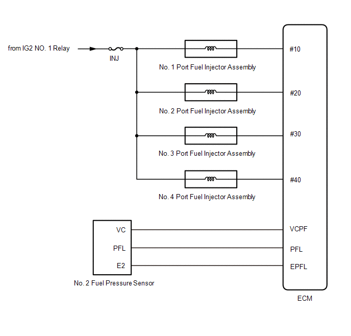
LOW PRESSURE SIDE FUEL SYSTEM WIRING DIAGRAM

READ NEXT:
 On-vehicle Inspection
ON-VEHICLE INSPECTION PROCEDURE 1. CHECK FUEL PUMP OPERATION AND INSPECT FOR FUEL LEAK (a) Check fuel pump operation. (1) Connect the Techstream to the DLC3. (2) Turn the power switch on (IG). NOTICE:
Components
COMPONENTS ILLUSTRATION *1 NO. 2 FLOOR UNDER COVER - - N*m (kgf*cm, ft.*lbf): Specified torque - - ILLUSTRATION *1 FUEL TANK ASSEMBLY *2 FUEL TANK MAIN TUBE SUB-ASSEM
SEE MORE:
Communication Error From Clearance Sonar ECU to VSC (C164B)
DESCRIPTION The electronically controlled brake system receives parking support brake system information from the clearance warning ECU assembly via CAN communication. When it is determined that there is a communication error between the skid control ECU and clearance warning ECU assembly, DTC C164B
Illumination for Panel Switch does not Come on with Tail Switch ON
CAUTION / NOTICE / HINT NOTICE:
Depending on the parts that are replaced during vehicle inspection or maintenance, performing initialization, registration or calibration may be needed. Refer to Precaution for Navigation System.
Click here
When replacing the radio receiver assembly, always re
© 2016-2026 Copyright www.lexguide.net
