Lexus ES: System Diagram
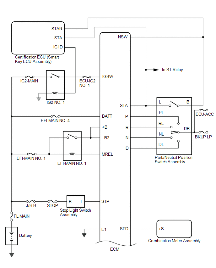
SYSTEM DIAGRAM
READ NEXT:
 Terminals Of Ecm
TERMINALS OF ECM ECM HINT: The standard voltage and resistance of each ECM terminal is shown in the table below. In the table, first follow the information under "Condition". Look under "Terminal No.
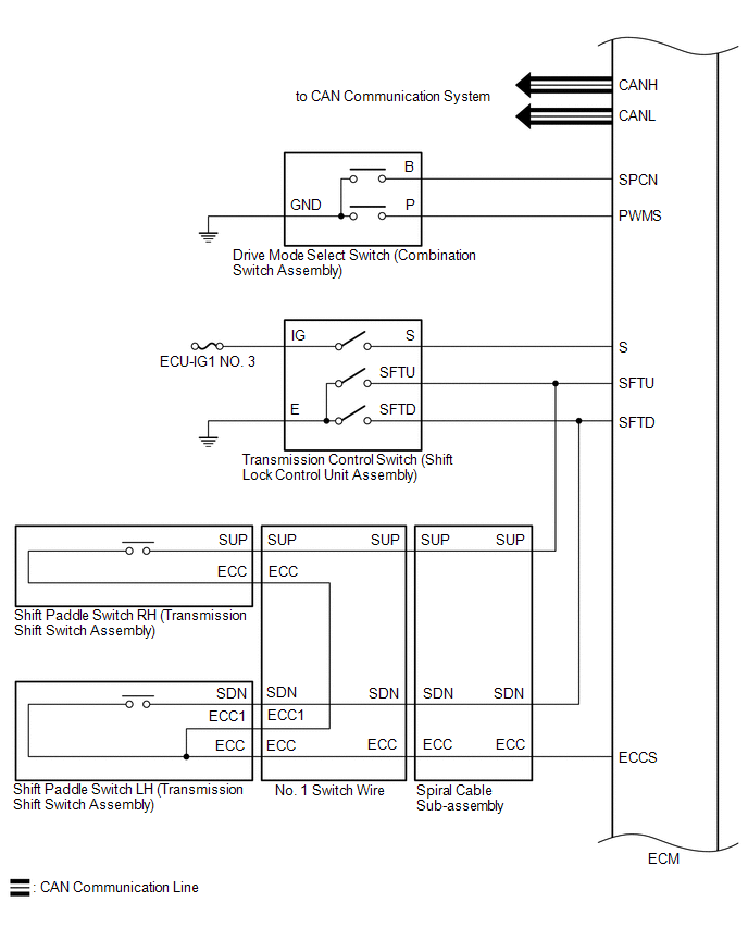
Transmission Control Switch Circuit
DESCRIPTION When the shift lever is in S and moved toward "-" or "+", it is possible to select different shift ranges (S1 to S8). Moving the shift lever toward "+" increases the shift range by one, an
Lost Communication with ECM/PCM "A" Missing Message (U010087)
DESCRIPTION The engine control unit and transmission control unit are located inside the ECM. The engine control unit intercommunicates with the transmission control unit using CAN communication. If t
SEE MORE:
Components
COMPONENTS ILLUSTRATION *A for Power Tilt and Power Telescopic Steering Column - - *1 STEERING WHEEL SWITCH HOUSING *2 TILT AND TELESCOPIC SWITCH *3 TURN SIGNAL SWITCH *4 WINDSHIELD WIPER SWITCH ASSEMBLY
Installation
INSTALLATION CAUTION / NOTICE / HINT NOTICE: This procedure includes the installation of small-head bolts. Refer to Small-Head Bolts of Basic Repair Hint to identify the small-head bolts. Click here PROCEDURE 1. INSTALL CAMSHAFT TIMING OIL CONTROL VALVE ASSEMBLY (EXHAUST CAMSHAFT TIMING GEAR BOLT
© 2016-2026 Copyright www.lexguide.net
