Lexus ES: Terminals Of Ecm
TERMINALS OF ECM
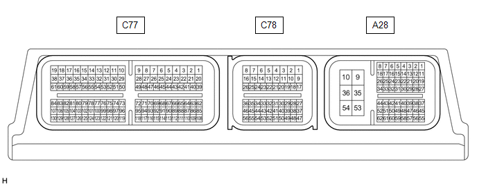
ECM
HINT:
The standard voltage and resistance of each ECM terminal is shown in the table below.
In the table, first follow the information under "Condition". Look under "Terminal No. (Symbol)" for the terminals to be inspected. The standard voltage or resistance between the terminals is shown under "Specified Condition".
Use the illustration above as a reference for the ECM terminals.
| Terminal No. (Symbol) | Wiring Color | Terminal Description | Condition | Specified Condition |
|---|---|---|---|---|
| A28-1 (BATT) - A28-10 (E1) | G - W-B | Battery (for measuring battery voltage and for ECM memory) | Always | 11 to 14 V |
| A28-8 (CANH) - A28-10 (E1) | B - W-B | CAN communication line | Engine switch on (IG) | Pulse generation |
| A28-9 (+B) - A28-10 (E1) | L - W-B | Power source of ECM | Engine switch on (IG) | 11 to 14 V |
| A28-10 (E1) - Body ground | W-B - Body ground | Ground | Always | Below 1 Ω |
| A28-12 (PWMS) - A28-10 (E1) | LG - W-B | Combination switch (S) signal | Engine switch on (IG) and combination switch assembly knob turned and held at S position | Below 1.5 V |
| Engine switch on (IG) and combination switch assembly knob not turned to S position | 11 to 14 V | |||
| A28-13 (SPCN) - A28-10 (E1) | P - W-B | Combination switch (Normal) signal | Engine switch on (IG) and Normal mode switch pushed and held | Below 1.5 V |
| Engine switch on (IG) and Normal mode switch not pushed | 11 to 14 V | |||
| A28-14 (S) - A28-10 (E1) | GR - W-B | S shift position switch signal | Engine switch on (IG) and shift lever in S | 11 to 14 V |
| Engine switch on (IG) and shift lever not in S | Below 1 V | |||
| A28-18 (CANL) - A28-10 (E1) | W - W-B | CAN communication line | Engine switch on (IG) | Pulse generation |
| A28-19 (SFTD) - A28-10 (E1) | W - W-B | Down-shift switch signal | Engine switch on (IG) | 11 to 14 V |
| Engine switch on (IG) and shift lever held in "-" (Down shift) | Below 1 V | |||
| A28-19 (SFTD) - A28-28 (ECCS) | W - BE | Down-shift switch signal | Engine switch on (IG) | 11 to 14 V |
| Engine switch on (IG) and "-" (Down shift) shift paddle switch operated | Below 1 V | |||
| A28-20 (SFTU) - A28-10 (E1) | G - W-B | Up-shift switch signal | Engine switch on (IG) | 11 to 14 V |
| Engine switch on (IG) and shift lever held in "+" (Up shift) | Below 1 V | |||
| A28-20 (SFTU) - A28-28 (ECCS) | G - BE | Up-shift switch signal | Engine switch on (IG) | 11 to 14 V |
| Engine switch on (IG) and "+" (Up shift) shift paddle switch operated | Below 1 V | |||
| A28-21 (STP) - A28-10 (E1) | SB - W-B | Stop light switch signal | Brake pedal depressed | 7.5 to 14 V |
| Brake pedal released | Below 1 V | |||
| A28-23 (NSW) - A28-10 (E1) | BE - W-B | Park/neutral position switch signal | Engine switch on (IG) and shift lever in P or N | Below 1 V |
| Engine switch on (IG) and shift lever not in P or N | 11 to 14 V | |||
| A28-30 (STA) - A28-10 (E1) | G - W-B | Starter signal | Cranking (shift lever in P or N, engine switch on (START)) | 11 to 14 V |
| Engine switch on (IG) and shift lever in P or N | Below 2 V | |||
| A28-35 (+B2) - A28-10 (E1) | L - W-B | Power source of ECM | Engine switch on (IG) | 11 to 14 V |
| A28-42 (SPD) - A28-10 (E1) | L - W-B | Vehicle speed signal from combination meter assembly | Driving at 20 km/h (12 mph) | Pulse generation |
| C78-2 (SL6+) - C78-1 (SL6-) | B - L | Solenoid (SL6) valve signal | 1st or Reverse gear selected | Pulse generation |
| C78-4 (SL3+) - C78-3 (SL3-) | G - R | Solenoid (SL3) valve signal | 3rd, 7th or Reverse gear selected | Pulse generation |
| C78-6 (SL2+) - C78-5 (SL2-) | R - GR | Solenoid (SL2) valve signal | 5th, 6th, 7th or 8th gear selected | Pulse generation |
| C78-8 (SL1+) - C78-7 (SL1-) | LG - L | Solenoid (SL1) valve signal | 1st, 2nd, 3rd, 4th or 5th gear selected | Pulse generation |
| C78-10 (SLT+) - C78-9 (SLT-) | GR - LG | Solenoid (SLT) valve signal | Engine idling | Pulse generation |
| C78-12 (SLU+) - C78-11 (SLU-) | LG - V | Solenoid (SLU) valve signal | Lock-up ON | Pulse generation |
| C78-14 (SL5+) - C78-13 (SL5-) | V - P | Solenoid (SL5) valve signal | 2nd or 8th gear selected | Pulse generation |
| C78-16 (SL4+) - C78-15 (SL4-) | G - B | Solenoid (SL4) valve signal | 4th or 6th gear selected | Pulse generation |
| C78-19 (SL) - A28-10 (E1) | P - W-B | Solenoid (SL) valve signal |
| 11 to 14 V |
| C78-23 (D) - A28-10 (E1) | R - W-B | D shift position switch signal | Engine switch on (IG) and shift lever in D or S | 11 to 14 V |
| Engine switch on (IG) and shift lever not in D or S | Below 1 V | |||
| C78-24 (N) - A28-10 (E1) | LG - W-B | N shift position switch signal | Engine switch on (IG) and shift lever in N | 11 to 14 V |
| Engine switch on (IG) and shift lever not in N | Below 1 V | |||
| C78-25 (R) - A28-10 (E1) | W - W-B | R shift position switch signal | Engine switch on (IG) and shift lever in R | 11 to 14 V |
| Engine switch on (IG) and shift lever not in R | Below 1 V | |||
| C78-26 (P) - A28-10 (E1) | B - W-B | P shift position switch signal | Engine switch on (IG) and shift lever in P | 11 to 14 V |
| Engine switch on (IG) and shift lever not in P | Below 1 V | |||
| C78-33 (NCB) - A28-10 (E1) | B - W-B | Power source for sensor (specific voltage) | Engine switch on (IG) | 11 to 14 V |
| C78-34 (NCO) - A28-10 (E1) | V - W-B | Transmission Revolution Sensor (NC) signal | Vehicle being driven | Pulse generation |
| C78-35 (NTB) - A28-10 (E1) | R - W-B | Power source for sensor (specific voltage) | Engine switch on (IG) | 11 to 14 V |
| C78-36 (NTO) - A28-10 (E1) | G - W-B | Transmission Revolution Sensor (NT) signal | Engine idling (shift lever in P or N) | Pulse generation |
| C78-46 (THO1) - C78-45 (ETHO) | LG - L | ATF temperature sensor signal | ATF temperature 115°C (239°F) or higher | Below 1.5 V |
READ NEXT:
 Transmission Control Switch Circuit
DESCRIPTION When the shift lever is in S and moved toward "-" or "+", it is possible to select different shift ranges (S1 to S8). Moving the shift lever toward "+" increases the shift range by one, an
Lost Communication with ECM/PCM "A" Missing Message (U010087)
DESCRIPTION The engine control unit and transmission control unit are located inside the ECM. The engine control unit intercommunicates with the transmission control unit using CAN communication. If t
SEE MORE:
Drive Motor "A" Inverter Stuck On (P0A789E,P1C5D19)
DTC SUMMARY MALFUNCTION DESCRIPTION This DTC indicates that a large current flowed through the motor inverter. The cause of this malfunction may be one of the following: Area Main Malfunction Description Hybrid vehicle transaxle assembly
Open or short circuit in the motor coils
Motor
Removal
REMOVAL CAUTION / NOTICE / HINT The necessary procedures (adjustment, calibration, initialization, or registration) that must be performed after parts are removed and installed, or replaced during cylinder head gasket removal/installation are shown below. Necessary Procedure After Parts Removed/Inst
