Lexus ES: Installation
INSTALLATION
CAUTION / NOTICE / HINT
NOTICE:
This procedure includes the installation of small-head bolts. Refer to Small-Head Bolts of Basic Repair Hint to identify the small-head bolts.
Click here .gif)
PROCEDURE
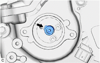
1. INSTALL CAMSHAFT TIMING OIL CONTROL VALVE ASSEMBLY (EXHAUST CAMSHAFT TIMING GEAR BOLT ASSEMBLY)
| (a) Type A: (1) Apply a light coat of engine oil to the O-ring of the camshaft timing oil control valve assembly (exhaust camshaft timing gear bolt assembly). NOTICE: If reusing the camshaft timing oil control valve assembly (exhaust camshaft timing gear bolt assembly), be sure to inspect the O-ring. (2) Temporarily install the camshaft timing oil control valve assembly (exhaust camshaft timing gear bolt assembly) to the camshaft timing exhaust gear assembly. NOTICE: If the camshaft timing oil control valve assembly (exhaust camshaft timing gear bolt assembly) has been struck or dropped, replace it. (3) Using a 5 mm hexagon socket wrench, install the camshaft timing oil control valve assembly (exhaust camshaft timing gear bolt assembly) with the bolt. Torque: 19 N·m {194 kgf·cm, 14 ft·lbf} |
|
.png)
(b) Type B:
(1) Temporarily install the camshaft timing oil control valve assembly (exhaust camshaft timing gear bolt assembly) to the camshaft timing exhaust gear assembly.
NOTICE:
- If the camshaft timing oil control valve assembly (exhaust camshaft timing gear bolt assembly) has been struck or dropped, replace it.
-
Make sure to fit the protrusion of the camshaft timing oil control valve assembly (exhaust camshaft timing gear bolt assembly) into the cutout of the camshaft timing exhaust gear assembly.
(2) Using a 5 mm hexagon socket wrench, install the camshaft timing oil control valve assembly (exhaust camshaft timing gear bolt assembly) with the bolt.
Torque:
19 N·m {194 kgf·cm, 14 ft·lbf}
(3) Pull the camshaft timing oil control valve assembly (exhaust camshaft timing gear bolt assembly) to confirm that is installed securely.
2. INSTALL CAM TIMING OIL CONTROL SOLENOID ASSEMBLY
Click here
READ NEXT:
 Camshaft Position Sensor
ComponentsCOMPONENTS ILLUSTRATION *1 NO. 1 ENGINE COVER SUB-ASSEMBLY *2 CAMSHAFT POSITION SENSOR (for Intake Side) *3 CAMSHAFT POSITION SENSOR (for Exhaust Side) - - N*m (k
Components
COMPONENTS ILLUSTRATION *1 CAM TIMING CONTROL MOTOR O-RING *2 CAM TIMING CONTROL MOTOR WITH EDU ASSEMBLY *3 NO. 1 ENGINE COVER SUB-ASSEMBLY - - N*m (kgf*cm, ft.*lbf): Specif
SEE MORE:
Luggage Compartment Door Opener does not Operate
DESCRIPTION The main body ECU (multiplex network body ECU) receives switch signals from the trunk and fuel switch assembly (luggage compartment door opening switch) the luggage door opening cancel switch, and operates the luggage compartment door lock assembly to open the luggage compartment door. W
Cooling Fan Circuit
DESCRIPTION The ECM calculates an appropriate cooling fan speed based on the engine coolant temperature, air conditioning switch status, refrigerant pressure, engine speed and vehicle speed, and sends a signal to the cooling fan ECU (fan with motor assembly). The cooling fan ECU (fan with motor asse
