Lexus ES: System Diagram
SYSTEM DIAGRAM
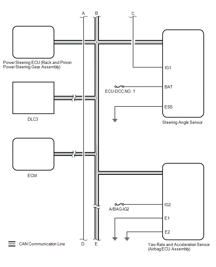
| Transmitting ECU (Transmitter) | Receiving ECU | Signal | Communication Method |
|---|---|---|---|
| Skid control ECU (brake actuator assembly) | Steering angle sensor | Steering angle sensor request signal | CAN communication line |
| Steering angle sensor | Skid control ECU (brake actuator assembly) | Steering angle sensor signal | CAN communication line |
| Skid control ECU (brake actuator assembly) | Yaw rate and acceleration sensor (airbag ECU assembly) | Yaw rate and acceleration request signal | CAN communication line |
| Yaw rate and acceleration sensor (airbag ECU assembly) | Skid control ECU (brake actuator assembly) | Yaw rate and acceleration signal | CAN communication line |
| Skid control ECU (brake actuator assembly) | ECM |
| CAN communication line |
| ECM | Skid control ECU (brake actuator assembly) |
| CAN communication line |
| Skid control ECU (brake actuator assembly) | Power steering ECU (rack and pinion power steering gear assembly) |
| CAN communication line |
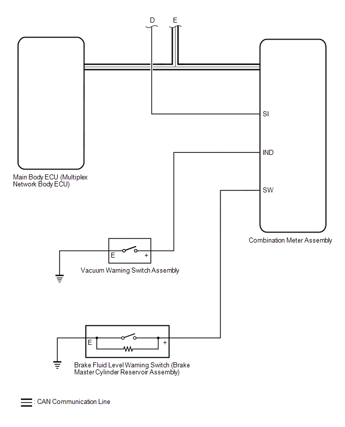
| Main body ECU (multiplex network body ECU) | Skid control ECU (brake actuator assembly) |
| CAN communication line |
| Skid control ECU (brake actuator assembly) | Combination meter assembly |
| CAN communication line |
| Airbag ECU assembly | Skid control ECU (brake actuator assembly) | Secondary collision brake request signal | CAN communication line |
READ NEXT:
 System Diagram
SYSTEM DIAGRAM Transmitting ECU (Transmitter) Receiving ECU Signal Communication Method Skid control ECU (brake actuator assembly) Steering angle sensor Steering angle sensor re
Terminals Of Ecu
TERMINALS OF ECU TERMINALS OF ECU *a Component without harness connected (Skid Control ECU (Brake Actuator Assembly)) - - HINT:
As a waterproof connector is used for the brake actuator
Test Mode Procedure
TEST MODE PROCEDURE NOTICE:
After replacing or removing and installing a speed sensor, perform Dealer Mode (Signal Check) inspection to confirm that the speed sensors are operating correctly.
Aft
SEE MORE:
Terminals Of Ecu
TERMINALS OF ECU CHECK OUTER MIRROR CONTROL ECU ASSEMBLY (DRIVER DOOR) (a) Disconnect the J28 outer mirror control ECU assembly (driver door) connector. (b) Measure the voltage and resistance according to the value(s) in the table below. HINT: Measure the values on the wire harness side with the co
Removal
REMOVAL CAUTION / NOTICE / HINT The necessary procedures (adjustment, calibration, initialization, or registration) that must be performed after parts are removed and installed, or replaced during telephone and GPS antenna assembly removal/installation are shown below. Necessary Procedure After Part
