Lexus ES: System Diagram
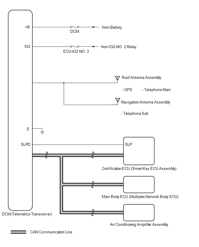
SYSTEM DIAGRAM
READ NEXT:
 Terminals Of Ecu
TERMINALS OF ECU HINT: Check from the rear of the connector while it is connected to the components. DCM (TELEMATICS TRANSCEIVER) Terminal No. (Symbol) Wiring Color Terminal Description Cond
Lost Communication with Body Control Module Missing Message (U014087,U015587,U016387)
DESCRIPTION These DTCs are stored when a malfunction occurs in the CAN communication circuit. DTC No. Detection Item DTC Detection Condition Trouble Area U014087 Lost Communication with
Utility
UTILITY CANCEL COMMUNICATION FUNCTION PAUSING HINT: This function is used to cancel communication function pausing mode. (a) Connect the Techstream to the DLC3. (b) Turn the engine switch on (IG). (c)
SEE MORE:
Glass Position Initialization Incomplete (B2313)
DESCRIPTION The power window regulator motor assemblies are operated by the multiplex network master switch assembly, power window regulator switch assembly or rear power window regulator switch assemblies. The power window regulator motor assembly has motor, regulator and ECU functions. When the EC
Lost Communication with ECM/PCM "A" Missing Message (U010087)
DESCRIPTION The engine control unit and transmission control unit are located inside the ECM. The engine control unit intercommunicates with the transmission control unit using CAN communication. If there is a problem in this intercommunication, the ECM stores this DTC. DTC No. Detection Item
© 2016-2026 Copyright www.lexguide.net
