Lexus ES: System Diagram
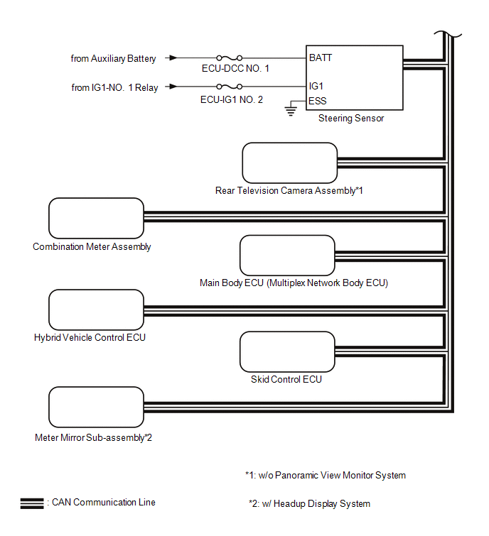
SYSTEM DIAGRAM
.png) for 12.3 inch display w/o Panoramic View Monitor System
for 12.3 inch display w/o Panoramic View Monitor System 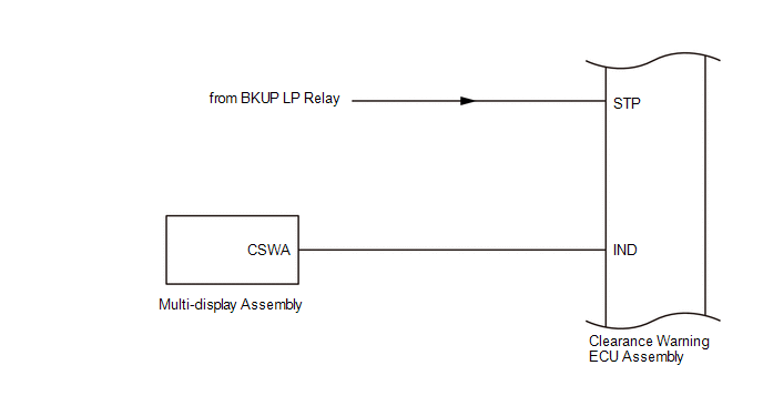
.png) w/ Blind Spot Monitor System
w/ Blind Spot Monitor System .png) w/ Panoramic View Monitor System
w/ Panoramic View Monitor System .png)
READ NEXT:
 Terminals Of Ecu
TERMINALS OF ECU CLEARANCE WARNING ECU ASSEMBLY (a) Disconnect the N41 clearance warning ECU assembly connector. (b) Measure the voltage and resistance on the wire harness side connector according to
The Display of the Multi-display does not Switched
DESCRIPTION The multi-display receives a signal from the clearance warning ECU assembly to change the display screen. WIRING DIAGRAM PROCEDURE 1. CHECK HARNESS AND CONNECTOR (CLEARANCE WARNING
Control Module Communication Bus "A" Off (U0073,U0126,U0129,U0140,U0155)
DESCRIPTION These DTCs are stored when the clearance warning ECU assembly cannot receive and recognize several signals via the CAN communication line. DTC No. Detection Item DTC Detection Condi
SEE MORE:
Crankshaft Position Sensor "A" Circuit Intermittent (P03351F,P03352A,P033531)
DESCRIPTION Refer to DTC P033511. Click here DTC No. Detection Item DTC Detection Condition Trouble Area MIL Memory Note P03351F Crankshaft Position Sensor "A" Circuit Intermittent Under conditions (a), (b) and (c), no crankshaft position sensor signal to ECM for 0.05 second
Lost Communication with Wiper ECU LIN (B1245)
DESCRIPTION The main body ECU (multiplex network body ECU) and windshield wiper motor assembly communicate via LIN communication. The main body ECU (multiplex network body ECU) stores this DTC if communication becomes abnormal. DTC No. Detection Item DTC Detection Condition Trouble Area M
© 2016-2026 Copyright www.lexguide.net
