Lexus ES: System Diagram
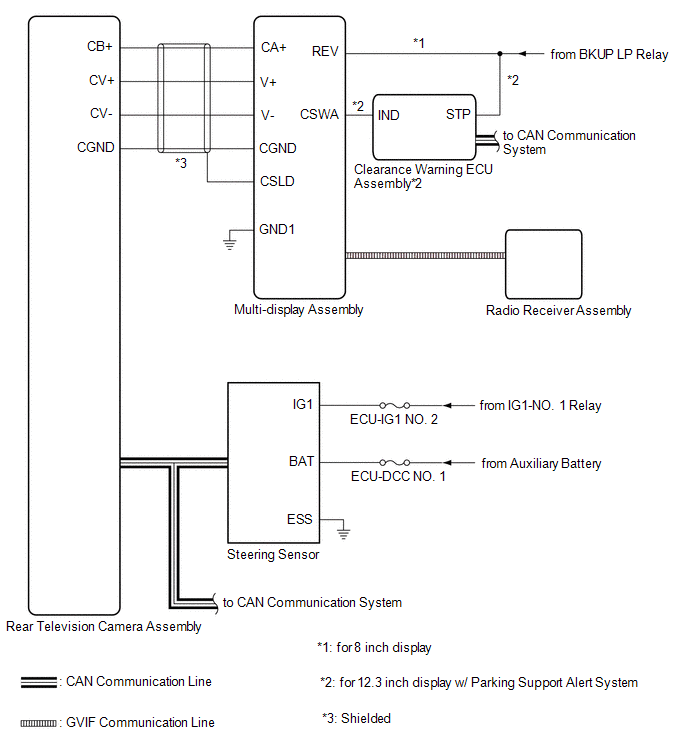
SYSTEM DIAGRAM
 Communication Table
 | Sender | Receiver | Signal | Line |
|---|---|---|---|
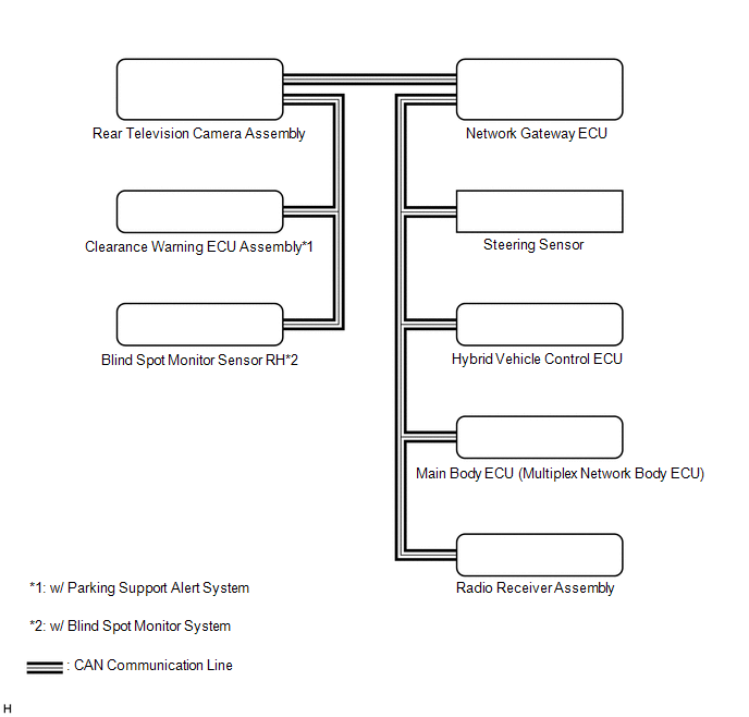
| Radio Receiver Assembly | Multi-display Assembly | Camera information signal | GVIF |
| Radio Receiver Assembly | Rear Television Camera Assembly | Setting information signal | CAN |
| Steering Sensor | Rear Television Camera Assembly | Steering angle signal | CAN |
| Hybrid Vehicle Control ECU | Rear Television Camera Assembly |
| CAN |
| Main Body ECU (Multiplex Network Body ECU) | Rear Television Camera Assembly |
| CAN |
| Blind Spot Monitor Sensor*1 | Rear Television Camera Assembly | RCTA information signal | CAN |
| Clearance Warning ECU Assembly*2 | Rear Television Camera Assembly | Sonar information signal | CAN |
- *1: w/ Blind Spot Monitor System
- *2: w/ Parking Support Alert System
READ NEXT:
 Terminals Of Ecu
TERMINALS OF ECU REAR TELEVISION CAMERA ASSEMBLY (a) Disconnect the T1 rear television camera assembly connector. (b) Measure the voltage on the wire harness side connector according to the value(s)
Lost Communication with ECM / PCM "A" (U0100,U0126,U0140,U0163,U0233,U1110)
DESCRIPTION These DTCs are stored if there is a malfunction in the CAN communication system connected to the rear television camera assembly. HINT: If CAN communication system DTCs are stored, they ma
CAN Communication Failure (Message Registry) (U1000)
DESCRIPTION This DTC is stored when the rear television camera assembly judges that it has an internal CAN malfunction. DTC No. Detection Item DTC Detection Condition Trouble Area U1000
SEE MORE:
Installation
INSTALLATION PROCEDURE 1. INSTALL SUSPENSION TOWER DAMPER (a) Install the suspension tower damper to the front bumper extension sub-assembly LH and front bumper extension sub-assembly RH with the 4 bolts. Torque: 27.5 N·m {280 kgf·cm, 20 ft·lbf} NOTICE: Do not extend or compress the damper. 2. I
Diagnostic Trouble Code Chart
DIAGNOSTIC TROUBLE CODE CHART LIN Communication System DTC No. Detection Item Link B1206 P/W Master Switch Communication Stop B1273 Sliding Roof ECU Communication Stop B2321 D-Door Motor ECU Communication Stop B2322 P-Door Motor ECU Communication Stop
© 2016-2026 Copyright www.lexguide.net
