Lexus ES: System Diagram
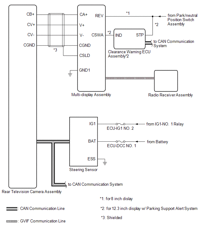
SYSTEM DIAGRAM
 Communication Table
 | Sender | Receiver | Signal | Line |
|---|---|---|---|
| Radio Receiver Assembly | Multi-display Assembly | Camera information signal | GVIF |
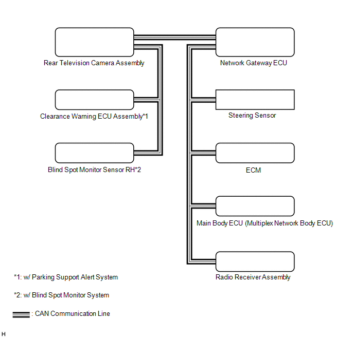
| Radio Receiver Assembly | Rear Television Camera Assembly | Setting information signal | CAN |
| Steering Sensor | Rear Television Camera Assembly | Steering angle signal | CAN |
| ECM | Rear Television Camera Assembly |
| CAN |
| Main Body ECU (Multiplex Network Body ECU) | Rear Television Camera Assembly |
| CAN |
| Blind Spot Monitor Sensor*1 | Rear Television Camera Assembly | RCTA information signal | CAN |
| Clearance Warning ECU Assembly*2 | Rear Television Camera Assembly | Sonar information signal | CAN |
- *1: w/ Blind Spot Monitor System
- *2: w/ Parking Support Alert System
READ NEXT:
 Terminals Of Ecu
TERMINALS OF ECU REAR TELEVISION CAMERA ASSEMBLY (a) Disconnect the T1 rear television camera assembly connector. (b) Measure the voltage on the wire harness side connector according to the value(s)
Lost Communication with ECM / PCM "A" (U0100,U0126,U0140,U0163,U0233,U1110)
DESCRIPTION These DTCs are stored if there is a malfunction in the CAN communication system connected to the rear television camera assembly. HINT: If CAN communication system DTCs are stored, they ma
CAN Communication Failure (Message Registry) (U1000)
DESCRIPTION This DTC is stored when the rear television camera assembly judges that it has an internal CAN malfunction. DTC No. Detection Item DTC Detection Condition Trouble Area U1000
SEE MORE:
Removal
REMOVAL PROCEDURE 1. REMOVE FRONT DOOR SCUFF PLATE LH Click here 2. REMOVE COWL SIDE TRIM BOARD LH Click here 3. REMOVE FRONT DOOR OPENING TRIM COVER LH Click here 4. REMOVE INSTRUMENT SIDE PANEL LH Click here 5. REMOVE NO. 1 INSTRUMENT PANEL UNDER COVER SUB-ASSEMBLY Click here 6. REM
Components
COMPONENTS
ILLUSTRATION
*1
FRONT WHEEL OPENING EXTENSION PAD RH
*2
FRONT WHEEL OPENING EXTENSION PAD LH
*3
NO. 1 ENGINE UNDER COVER
*4
NO. 2 ENGINE UNDER COVER ASSEMBLY
N*m (kg
© 2016-2026 Copyright www.lexguide.net
