Lexus ES: System Diagram
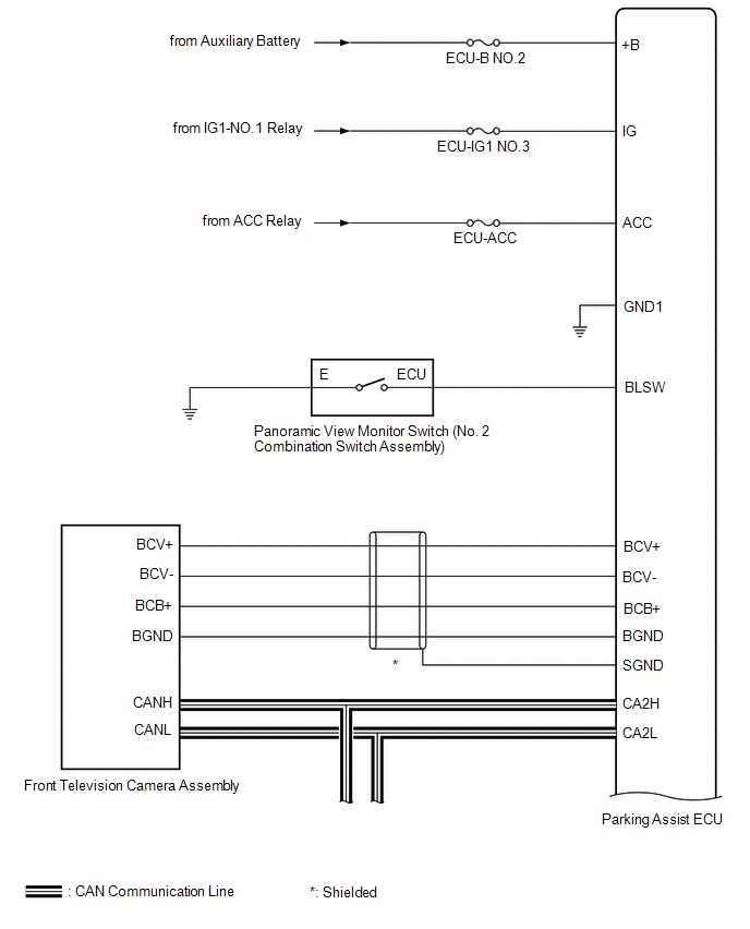
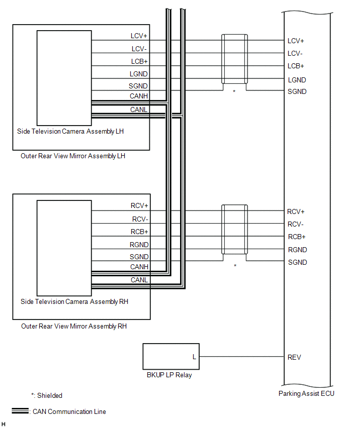
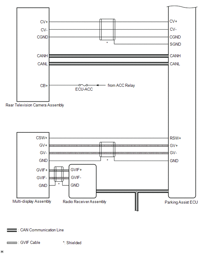
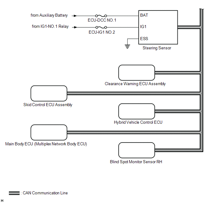
SYSTEM DIAGRAM
READ NEXT:
 Terminals Of Ecu
TERMINALS OF ECU PARKING ASSIST ECU (a) Disconnect the N44 parking assist ECU connector. (b) Measure the voltage and resistance according to the value(s) in the table below. Terminal No. (Symbol)
Lost Communication with Panoramic View Monitor Control Module (U023B)
DESCRIPTION These DTCs are stored if there is a malfunction in the CAN communication system connected to the rear television camera assembly. HINT: If CAN communication system DTCs are stored, they ma
Control Module Communication Bus Off (U0073,U0100,U0126,U0129,U0140,U0163,U0233,U023B,U0265,U0293,U1110)
DESCRIPTION These DTCs are stored if there is a malfunction in the CAN communication system connected to the parking assist ECU. HINT: If CAN communication system DTCs are stored, they may also be sto
SEE MORE:
Inspection
INSPECTION PROCEDURE 1. INSPECT OUTER REAR VIEW MIRROR ASSEMBLY RH (a) Check the operation of the mirror surface. NOTICE: If the mirror surface is fully turned to the right, left, upward or downward position, the motor slips and produces a clicking noise. This is not a malfunction. (1) Disconnect
Removal
REMOVAL CAUTION / NOTICE / HINT The necessary procedures (adjustment, calibration, initialization or registration) that must be performed after parts are removed and installed, or replaced during starter assembly removal/installation are shown below. Necessary Procedures After Parts Removed/Installe
© 2016-2026 Copyright www.lexguide.net
