Lexus ES: System Description
SYSTEM DESCRIPTION
GENERAL
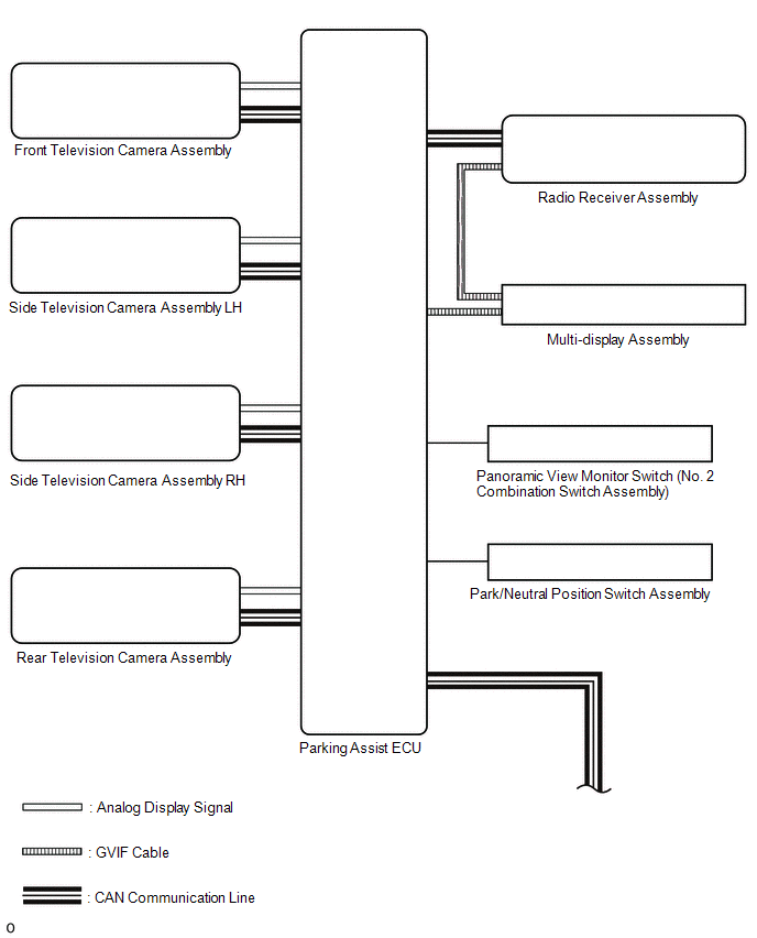
(a) This system has front, passenger side, driver side and rear television camera assemblies mounted around the vehicle to display around the vehicle on the multi-display assembly. The display panel also shows a composite view consisting of the area behind the vehicle and parking guidelines to assist the driver in parking the vehicle by monitoring the area around the vehicle.
(b) This system consists of the following components:
(1) Parking assist ECU
(2) Panoramic view monitor switch (No. 2 combination switch assembly)
(3) Rear television camera assembly
(4) Front television camera assembly
(5) Side television camera assembly LH
(6) Side television camera assembly RH
(7) Multi-display assembly
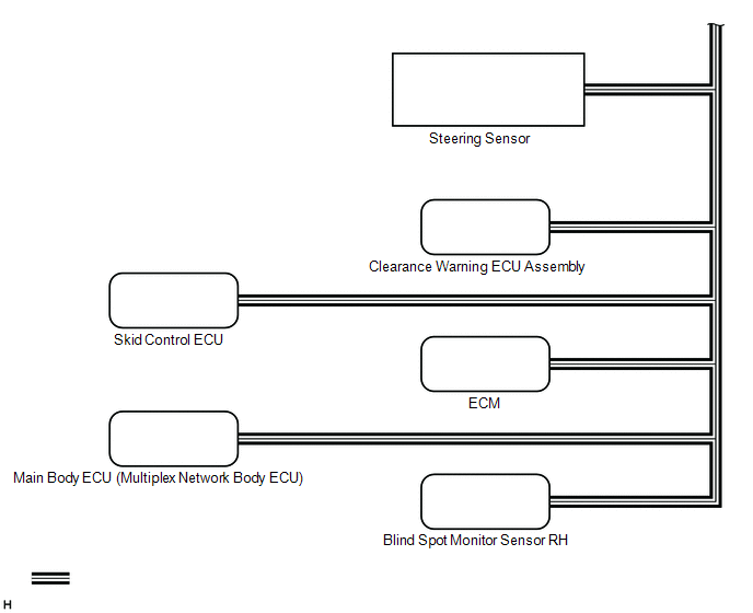
(8) Network gateway ECU
(9) Steering Sensor
(10) Skid control ECU
(11) Main body ECU (multiplex network body ECU)
(12) Clearance warning ECU assembly
(13) ECM
(14) Blind spot monitor sensor
(15) Radio receiver assembly
(c) This system is equipped with a self-diagnosis system, which is operated from a designated window that appears on the multi-display assembly, just as in the audio and visual system*1 or navigation system*2.
- *1: w/o Navigation System
- *2: w/ Navigation System
FUNCTION OF COMPONENTS
(a) The parking assist ECU controls the system by using information from the following components.
| Item | Function |
|---|---|
| Rear Television Camera Assembly |
|
| Front Television Camera Assembly | Generates a video feed showing the front side of the vehicle and transmits the video to the parking assist ECU |
| Side Television Camera Assembly LH | Generates a video feed showing the left side of the vehicle and transmits the video to the parking assist ECU |
| Side Television Camera Assembly RH | Generates a video feed showing the right side of the vehicle and transmits the video to the parking assist ECU |
| Parking Assist ECU |
|
| Panoramic View Monitor Switch (NO. 2 Combination Switch Assembly) | Transmits switch operation signals to the parking assist ECU |
| Multi-display Assembly | Displays image information received from the parking assist ECU. |
| Radio Receiver Assembly |
|
| Steering Sensor | Transmits the steering angle signals and sensor status signals to the parking assist ECU via the CAN communication |
| Skid Control ECU | Transmits the vehicle speed signals, drive type signals, and system status signals to the parking assist ECU via the CAN communication |
| ECM |
|
| Park/Neutral Position Switch Assembly | Sends the shift position signal to the parking assist ECU and ECM. |
| Main Body ECU (Multiplex Network Body ECU) |
|
| Clearance Warning ECU Assembly | Transmits information from each sonar via the CAN communication |
| Blind Spot Monitor Sensor | Transmits the RCTA information signal via CAN communication |
PANORAMIC VIEW SCREEN DISPLAY
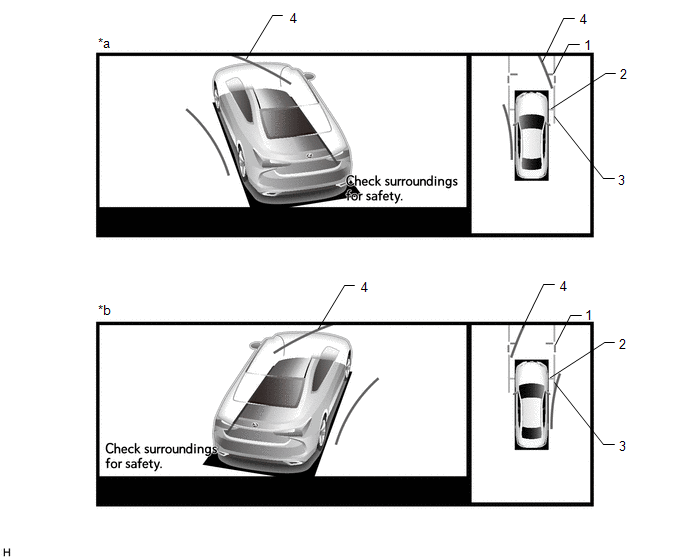
(a) See-through view screen
(1) The entire area surrounding the vehicle is displayed.
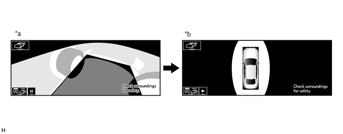
| *a | Vehicle interior view | *b | Upper view |
(b) Moving view screen
(1) The entire area surrounding the vehicle is displayed.
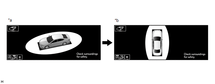
| *a | Slant upper view | *b | Upper view |
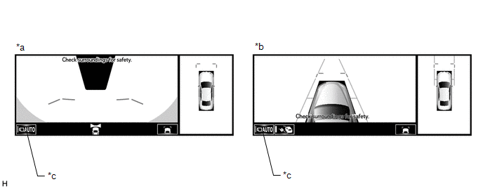
(c) Panoramic view and Cornering view screen (Models with 12.3 Inch Multi-display)
| *a | When turning left | *b | When turning right |
| Signal | Name | Color |
|---|---|---|
| (1) | Front distance guide line | Blue |
| (2) | Front wheel ground contact line | Gray |
| (3) | Vehicle width parallel line | Gray |
| (4) | Forward estimated course line | Yellow |
(d) Panoramic view and wide front view screen
| *a | Estimated course line display mode | *b | Distance guide line display mode |
| Signal | Name | Color | Panoramic View and Wide Front View Screen | |
|---|---|---|---|---|
| Estimated course line display mode | Distance guide line display mode | |||
| (1) | Front distance guide line | Blue | Displayed | Displayed |
| (2) | Front forward estimated course line | Yellow | Displayed | Not displayed |
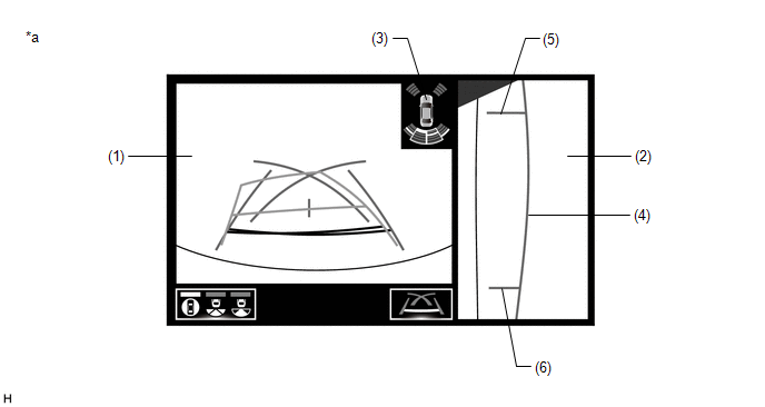
(e) Panoramic View and Side Clearance View Screen (Models with 12.3 Inch Multi-display)
| *a | When the outer rear view mirror assembly is deployed. | - | - |
| Signal | Name | Color |
|---|---|---|
| (1) | Front distance guide line | Blue |
| (2) | Front wheel ground contact line | Gray |
| (3) | Vehicle width parallel line | Gray |
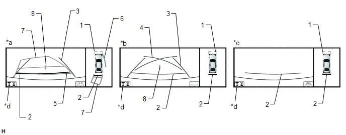
(f) Panoramic view and rear view screen
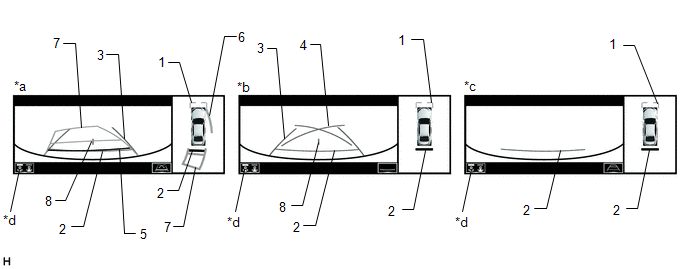
| *a | Estimated course line display mode | *b | Parking guide line display mode |
| *c | Distance guide line display mode | *d | Display mode switching button |
HINT:
The screen changes to the wide rear view screen when the display mode switch button or rear view screen is selected.
Panoramic View and Rear View Screen Description| Signal | Name | Color | Panoramic View and Rear View Screen | ||
|---|---|---|---|---|---|
| Estimated course line display mode | Parking guide line display mode | Distance guide line display mode | |||
| (1) | Front distance guide line | Blue | Displayed | Displayed | Displayed |
| (2) | Rear distance guide line | Red | Displayed | Displayed | Displayed |
| (3) | Rear vehicle width extension line | Blue | Displayed | Displayed | Not displayed |
| (4) | Parking guide line | Blue | Not displayed | Displayed | Not displayed |
| (5) | Rear distance guide line | Blue | Displayed | Not displayed | Not displayed |
| (6) | Side estimated course line | Yellow | Displayed | Not displayed | Not displayed |
| (7) | Rear estimated course line | Yellow | Displayed | Not displayed | Not displayed |
| (8) | Vehicle center line | Blue | Displayed | Displayed | Not displayed |
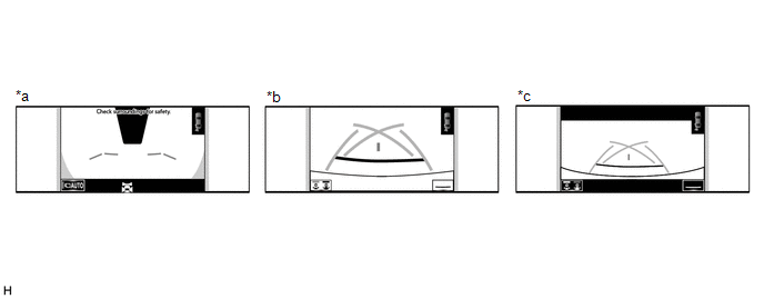
(g) Panoramic view and rear view screen
| *a | Estimated course line display mode | *b | Parking guide line display mode |
| *c | Distance guide line display mode | *d | Display mode switching button |
HINT:
In the rear view screen, the screen display mode can be switched by pressing the guide line display mode switching button or rear view screen on the screen.
Panoramic View and Rear View Screen Description| Signal | Name | Color | Panoramic View and Rear View Screen | ||
|---|---|---|---|---|---|
| Estimated course line display mode | Parking guide line display mode | Distance guide line display mode | |||
| (1) | Front distance guide line | Blue | Displayed | Displayed | Displayed |
| (2) | Rear distance guide line | Red | Displayed | Displayed | Displayed |
| (3) | Rear vehicle width extension line | Blue | Displayed | Displayed | Not displayed |
| (4) | Parking guide line | Blue | Not displayed | Displayed | Not displayed |
| (5) | Rear distance guide line | Blue | Displayed | Not displayed | Not displayed |
| (6) | Side estimated course line | Yellow | Displayed | Not displayed | Not displayed |
| (7) | Rear estimated course line | Yellow | Displayed | Not displayed | Not displayed |
| (8) | Vehicle center line | Blue | Displayed | Displayed | Not displayed |
(h) Side view screen (Models with 12.3 Inch Multi-display)
| *a | Side view and wide front view screen | *b | Side view and rear view screen |
| *c | Side view and wide rear view screen | - | - |
HINT:
Refer to the content of panoramic view and rear view screen and panoramic view and wide front view screen for information about the rear view and wide front view screens.
(i) Rear camera detection function screen
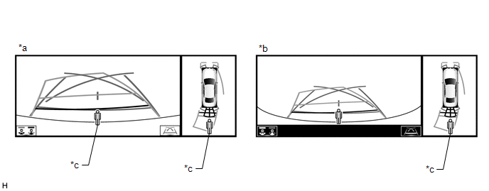
| *a | Panoramic view and rear view screen | *b | Panoramic view and wide rear view screen |
| *c | Rear camera detection icon | - | - |
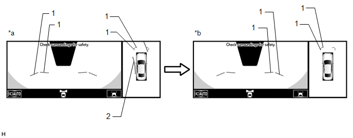
(j) Side View and Wide Front View Screen (Models with 8 Inch Multi-display)
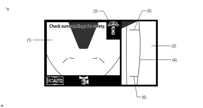
| *a | When the outer rear view mirrors are retracted | - | - |
| Item | Description | |
|---|---|---|
| (1) | Wide Front View | An image captured by the front television camera assembly of the area in front of the vehicle. |
| (2) | Side View (Right Side) | An image of the area to the right of the vehicle captured by the side television camera assembly RH. |
| (3) | Intuitive Parking Assist Information | If a stationary object is detected when the intuitive parking assist is activated, the approximate distance between the vehicle and the stationary object is displayed. |
| (4) | Vehicle Width Parallel Line (Blue) | A vehicle width guide line including the outer rear view mirror assembly. |
| (5) | Front Tire Contact Line (Blue) | A guide line showing the front right tire contact position. |
| (6) | Rear Tire Contact Line (Blue) | A guide line showing the rear right tire contact position. |
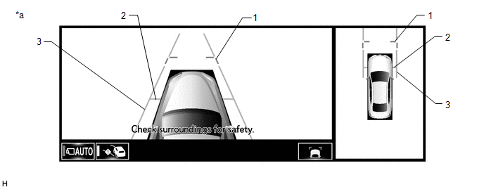
(k) Side View and Rear View Screen (Models with 8 Inch Multi-display)
| *a | When the outer rear view mirrors are retracted | - | - |
| Item | Description | |
|---|---|---|
| (1) | Rear View | An image captured by the rear television camera assembly of the area to the rear of the vehicle. |
| (2) | Side View (Right Side) | An image of the area to the right of the vehicle captured by the side television camera assembly RH. |
| (3) | Intuitive Parking Assist Information | If a stationary object is detected when the intuitive parking assist is activated, the approximate distance between the vehicle and the stationary object is displayed. |
| (4) | Vehicle Width Parallel Line (Blue) | A vehicle width guide line including the outer rear view mirror assembly. |
| (5) | Front Tire Contact Line (Blue) | A guide line showing the front right tire contact position. |
| (6) | Rear Tire Contact Line (Blue) | A guide line showing the rear right tire contact position. |
(l) Two-side View Screen (Models with 8 Inch Multi-display)
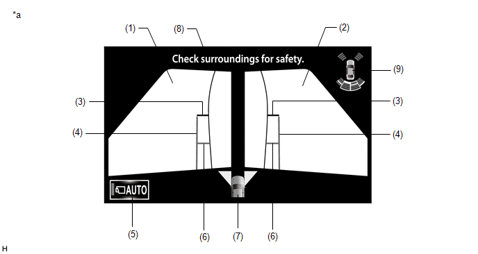
| *a | When the outer rear view mirror assembly is deployed. | - | - |
| Item | Description | |
|---|---|---|
| (1) | Side View (Front Left Side) | An image captured by the side television camera assembly LH of the area to the front left side of the vehicle. |
| (2) | Side View (Front Right Side) | An image captured by the side television camera assembly RH of the area to the front right side of the vehicle. |
| (3) | Front Distance Guide Line (Red) | These lines are distance guide lines showing the distance forward from the edge of the front bumper. (Approximately 0.5 m (1.6 ft.)) |
| (4) | Vehicle Width Parallel Line (Blue) | A vehicle width guide line including the outer rear view mirror assembly. |
| (5) | Auto Mode Button | Can be used to turn the automatic display mode on and off. When the automatic display mode is on, an indicator inside the button illuminates. |
| (6) | Front Tire Contact Line (Blue) | A guide line showing the front tire contact position. |
| (7) | Camera Direction Display Vehicle Icon | Indicates that the "side simultaneous view" is displayed. |
| (8) | Warning Message | Warns the driver according to the message on the display. |
| (9) | Intuitive Parking Assist Information |
|
PANORAMIC VIEW SCREEN DESCRIPTION
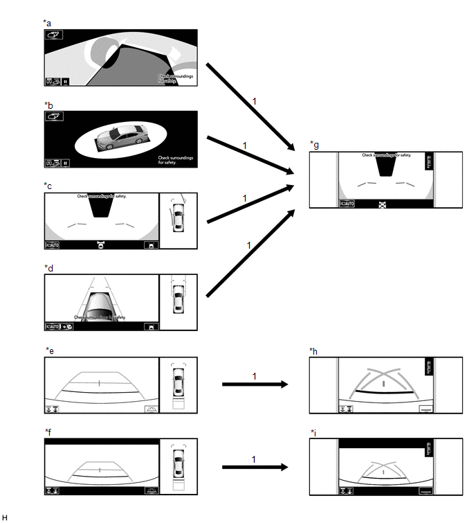
(a) Manual display mode
(1) When the panoramic view monitor switch is pressed with the engine switch on (IG) or the engine started, the panoramic view monitor system switches to a screen shown below according to the shift lever position
Screen Transition Chart (Manual Display Mode with 12.3 Inch Multi-display)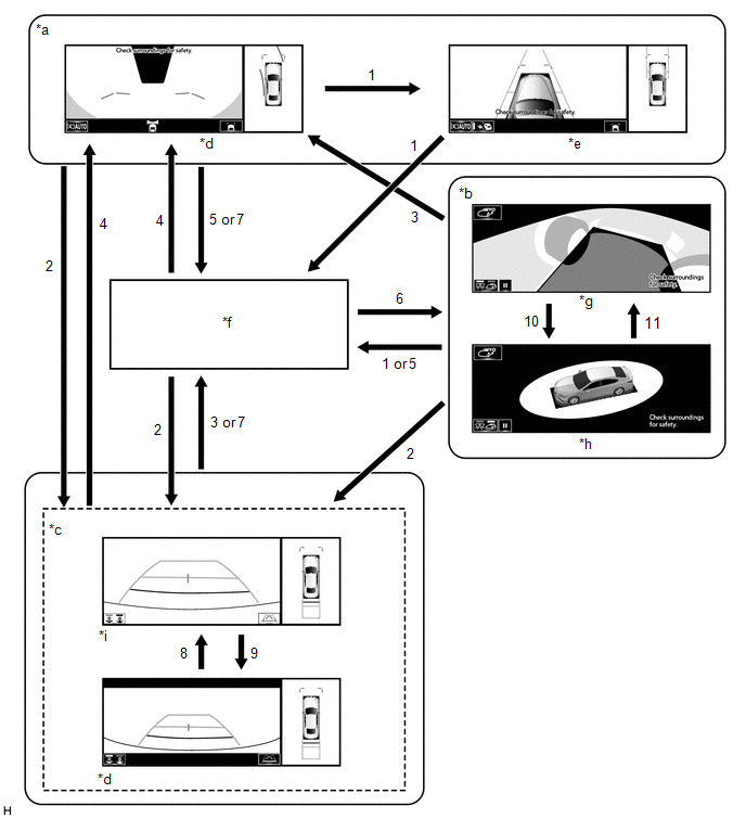
| *a | Shift position in any position other than P or R. | *b | Shift position in P and intelligent clearance sonar system on |
| *c | Shift position in R | *d | Panoramic view and wide rear view screen |
| *e | Panoramic view and side clearance view screen | *f | Navigation screen, etc. |
| *g | See-through view screen | *h | Moving view screen |
| *i | Panoramic view and rear view screen | - | - |
| No. | Screen Transition Conditions |
|---|---|
| (1) | Panoramic view monitor main switch is pressed |
| (2) | Shift position is moved to R |
| (3) | Shift position is moved to other than P or R |
| (4) | Shift position is moved to other than P or R and operation (1) is performed |
| (5) | "MAP/VOICE" switches, etc. on the multi-display assembly are pressed |
| (6) | Operation (1) is performed with the shift position in P |
| (7) | Shift position is moved to P |
| (8) | Display mode switching button or wide rear view screen is selected |
| (9) | Display mode switching button or rear view screen is selected |
| (10) | Moving view switch button is selected |
| (11) | See through view switch button is selected |
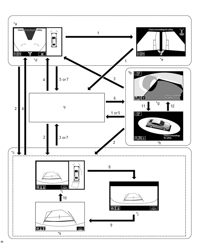
| *a | Shift lever not in P or R | *b | Shift lever in P and intelligent clearance sonar system system on |
| *c | Shift lever in R | *d | Panoramic view and wide front view screen |
| *e | Two-side view screen | *f | Audio screen, etc. |
| *g | See-through view screen | *h | Moving view screen |
| *i | Panoramic view and rear view screen | *j | Wide rear view screen |
| *k | Narrow rear view screen | - | - |
| No. | Screen Transition Conditions |
|---|---|
| (1) | Panoramic view monitor switch is pressed |
| (2) | Shift lever is moved to R |
| (3) | Shift lever is moved to other than P or R |
| (4) | Shift lever is moved to other than P or R and operation (1) is performed |
| (5) | "HOME" switches, etc. on the multi-display assembly are pressed |
| (6) | Operation (1) is performed with the shift lever in P |
| (7) | Shift lever is moved to P |
| (8) | Display mode switching button or rear view screen is selected |
| (9) | Display mode switching button or wide rear view screen is selected |
| (10) | Display mode switching button or narrow rear view screen is selected |
| (11) | Moving view switch button is selected |
| (12) | See through view switch button is selected |
HINT:
If the panoramic view monitor main switch is pressed at a vehicle speed of approximately 12 km/h (7 mph) or lower, the panoramic view monitor system screen is displayed. If the vehicle speed exceeds approximately 12 km/h (7 mph), the display switches to the navigation screen or information settings screen.
(b) Screen transition chart (automatic display mode)
(1) When the shift position is not in P or R, in addition to switching screens by pressing the panoramic view monitor main switch, the automatic display mode can be selected by pressing the automatic display mode switching button.
| *a | Panoramic view and wide front view screen | *b | Panoramic view and side clearance view screen |
| *c | Automatic display mode switching button | - | - |
| Automatic Display Mode Switching Button (Indicator in Button) | Screen Switching Mode |
|---|---|
| ON (Illuminated) | Automatic display mode |
| OFF (Not illuminated) | Manual display mode |
HINT:
- In the automatic display mode, press the panoramic view monitor switch or panel switch to switch screens in the same way as the manual display mode.
- When switching to the audio screen, etc. in the automatic display mode, the display switches to the screen that was displayed last. However, the display switches to the panoramic view and wide front view screen if the shift lever is not in P or R after the engine switch is turned from off to on (IG).
(2) The automatic display mode automatically switches the display according to the vehicle status.
Screen Transition Chart (Automatic Display Mode)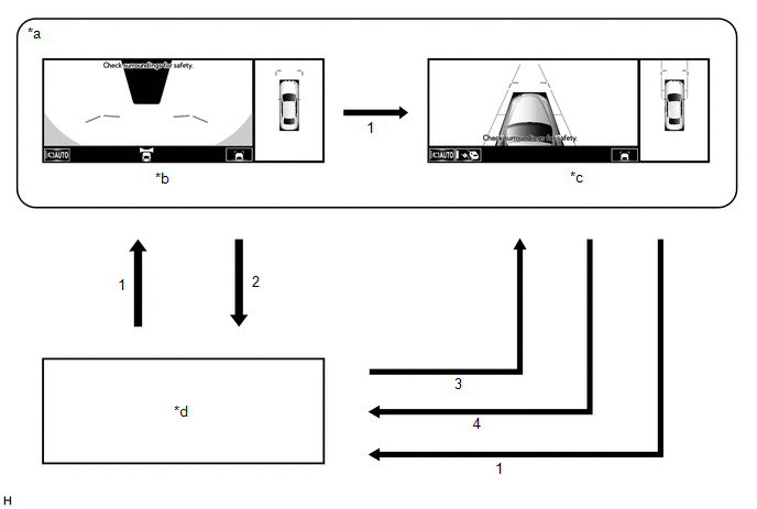
| *a | Shift position in any position other than P or R. | *b | Panoramic view and wide front view screen |
| *c | Panoramic view and side clearance view screen | *d | Navigation screen, etc. |
| No. | Screen Transition Conditions |
|---|---|
| *: The panoramic view and wide front view screen is the first screen displayed after the engine switch was turned off. | |
| (1) | Panoramic view monitor switch is pressed |
| (2) | Current location switches, etc. on the multi-display assembly are pressed |
| (3) | Vehicle speed changes from above approximately 10 km/h (6 mph) to approximately 10 km/h (6 mph) or lower. The screen that was last displayed is displayed on the multi-display assembly.* |
| (4) | Vehicle speed changes from approximately 12 km/h (7 mph) or lower to above approximately 12 km/h (7 mph) |
(c) Panoramic View Zoom Function (Models with 12.3 Inch Multi-display)
(1) When detail within the image on the panoramic view screen is too small and difficult to see, the user can magnify the image by selecting one of the 2 areas on the panoramic view screen.
Screen Transition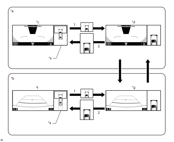
| *a | Panoramic view and wide front view screen displayed while shift lever is not in P or R | *b | Panoramic view and rear view screen displayed |
| *c | Panoramic view and wide front view screen | *d | Panoramic view and wide front view screen (Front view magnified) |
| *e | Panoramic view screen | *f | Panoramic view and rear view screen |
| *g | Panoramic view and rear view screen (Front view magnified) | - | - |
| No. | Screen Transition Conditions |
|---|---|
| (1) | Any of the 2 areas on the panoramic view screen is selected while the vehicle speed is approximately 12 km/h (7 mph) or less and the intelligent clearance sonar system is turned on. |
| (2) | The panoramic view zoom screen is selected, or either of the following conditions is met:
|
(d) Panoramic View Zoom Function (Models with 8 Inch Multi-display)
(1) When detail within the image on the panoramic view screen is too small and difficult to see, the user can magnify the image by selecting one of the 4 areas on the panoramic view screen.
Screen Transition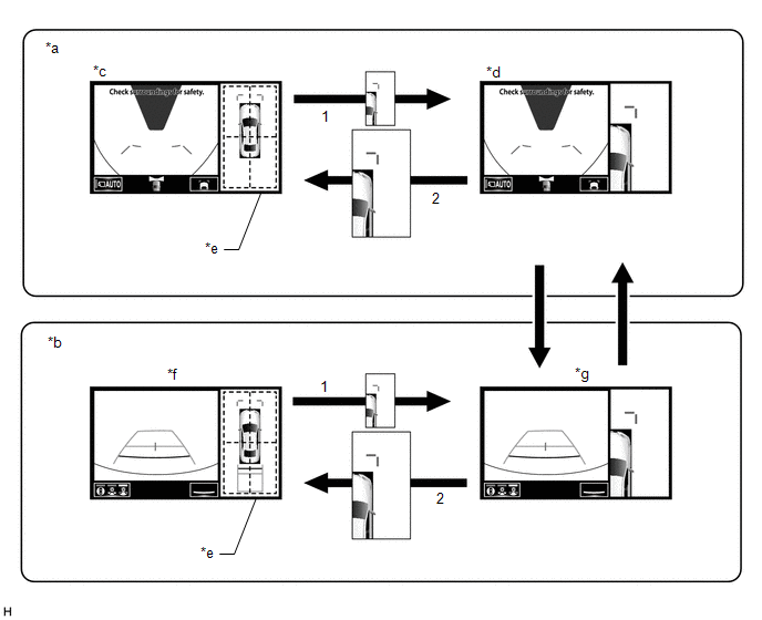
| *a | Panoramic view and wide front view screen displayed while shift lever is not in P or R | *b | Panoramic view and rear view screen displayed |
| *c | Panoramic view and wide front view screen | *d | Panoramic view and wide front view screen (Front right view magnified) |
| *e | Panoramic view screen | *f | Panoramic view and rear view screen |
| *g | Panoramic view and rear view screen (Front right view magnified) | - | - |
| No. | Screen Transition Conditions |
|---|---|
| (1) | Any of the 4 areas on the panoramic view screen is selected while the vehicle speed is approximately 12 km/h (7 mph) or less and the intelligent clearance sonar system is turned on. |
| (2) | The panoramic view zoom screen is selected, or either of the following conditions is met:
|
(e) When the outer rear view mirror assembly is retracted
(1) When the outer rear view mirrors are retracted, the screen changes according to the current screen display, as follows.
| *a | See through view screen | *b | Moving view screen |
| *c | Panoramic view and wide front view screen | *d | Panoramic view and side clearance view screen |
| *e | Panoramic view and rear view screen | *f | Panoramic view and wide rear view screen |
| *g | Two side view and wide front view screen | *h | Two side view and rear view screen |
| *i | Two side view and wide rear view screen | - | - |
| No. | Screen Transition Conditions |
|---|---|
| (1) | When outer rear view mirror assembly is retracted |
COMMUNICATION SYSTEM OUTLINE
(a) CAN communication system
(1) The panoramic view monitor system uses CAN communication for data communications between the parking assist ECU and each ECU.
(2) If a problem occurs in the CAN communication line, the parking assist ECU outputs a CAN communication malfunction DTC. (To check, use the Techstream.)
Click here .gif)
(3) If a problem occurs in the CAN communication line, the parking assist ECU outputs a CAN communication malfunction DTC. (To check, use the multi-display assembly diagnosis screen.)
Click here
(4) If a CAN communication line malfunction DTC is output, repair the malfunction in the communication line and troubleshoot the panoramic view monitor system when data communication is normal.
(5) Since the CAN communication line has its own length and route, it cannot be repaired temporarily with a bypass wire, etc.
VIDEO SIGNALS
(a) Video signal circuit
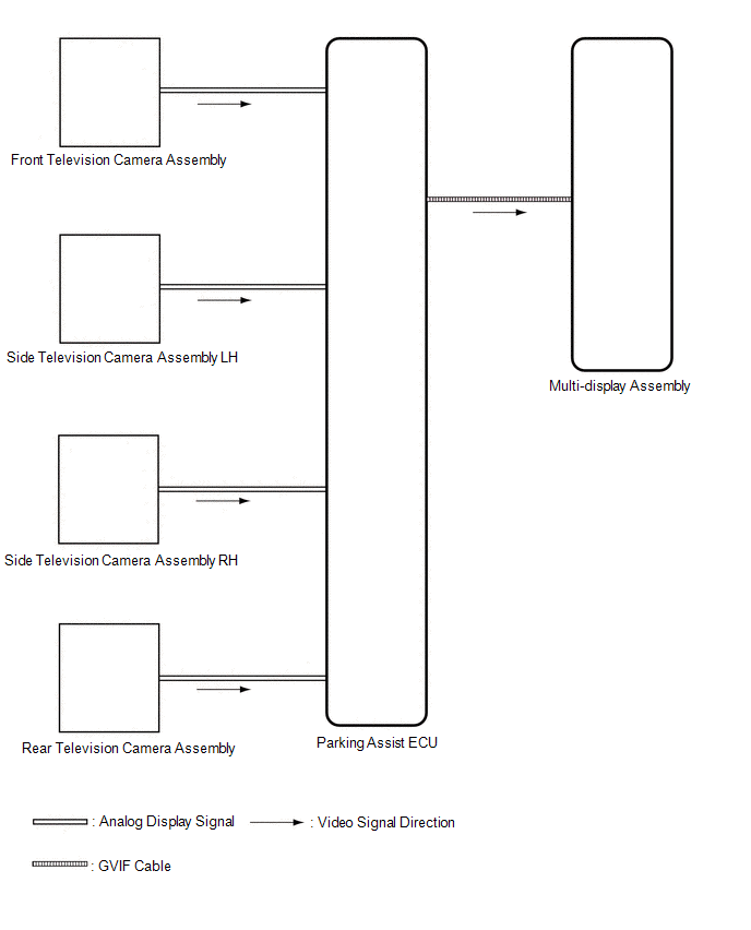
(1) Video signals from the front television camera assembly are input into the parking assist ECU via analog communication lines (vehicle wire harness).
(2) Video signals from the side television camera assembly LH are input into the parking assist ECU via analog communication lines (vehicle wire harness).
(3) Video signals from the side television camera assembly RH are input into the parking assist ECU via analog communication lines (vehicle wire harness).
(4) Video signals from the rear television camera assembly are input into the parking assist ECU via analog communication lines (vehicle wire harness).
(5) Video signals from the parking assist ECU are input into the multi-display assembly via GVIF cable.
(b) Screen display
(1) Video signals input from each camera are processed in the parking assist ECU and displayed on the multi-display assembly as the panoramic view monitor system screen.
DIAGNOSTIC FUNCTION OUTLINE
(a) This panoramic view monitor system has a diagnostic function displayed in the multi-display assembly. This function enables the calibration (adjustment and verification) of the panoramic view monitor system.
Click here
(b) The panoramic view monitor system can check the following items by using the Techstream.
| Item | Proceed to |
|---|---|
| DTC | |
| Data List / Active Test | |
CALIBRATION
(a) Use the panoramic view monitor system diagnosis screen for calibration and checking of the panoramic view monitor system.
Click here
NOTICE:
Part replacement and work performed during servicing may require calibration of the panoramic view monitor system and other systems.
Click here
READ NEXT:
 System Diagram
SYSTEM DIAGRAM
Terminals Of Ecu
TERMINALS OF ECU PARKING ASSIST ECU (a) Disconnect the N44 parking assist ECU connector. (b) Measure the voltage and resistance according to the value(s) in the table below. Terminal No. (Symbol)
Lost Communication with Panoramic View Monitor Control Module (U023B)
DESCRIPTION These DTCs are stored if there is a malfunction in the CAN communication system connected to the rear television camera assembly. HINT: If CAN communication system DTCs are stored, they ma
SEE MORE:
Components
COMPONENTS ILLUSTRATION *A for HV Model *B for Gasoline Model *1 REAR DOOR SCUFF PLATE LH *2 REAR DOOR SCUFF PLATE RH *3 REAR SEAT SIDE GARNISH LH *4 REAR SEAT SIDE GARNISH RH *5 ROOF SIDE INNER GARNISH ASSEMBLY LH *6 ROOF SIDE INNER GARNISH ASSEMBLY RH *7
Visual Mute Signal Circuit between Radio Receiver and Multi-display
DESCRIPTION The radio receiver assembly sends a visual mute signal to the multi-display assembly. As a result, a black screen is displayed when the screen changes so that noise and distorted images are not displayed. When an open exists in the circuit, noise and distorted images will be displayed in
