Lexus ES: System Diagram
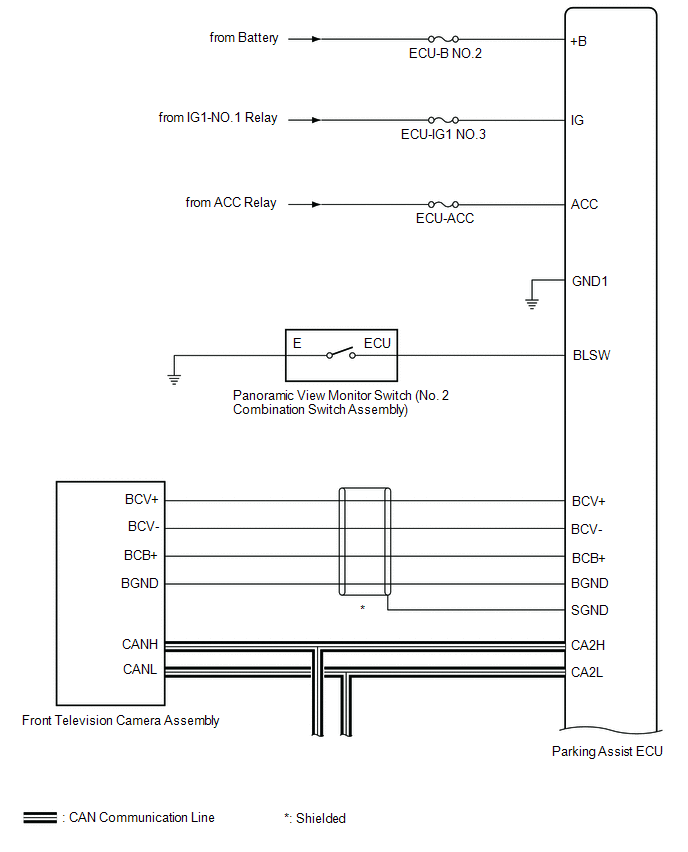
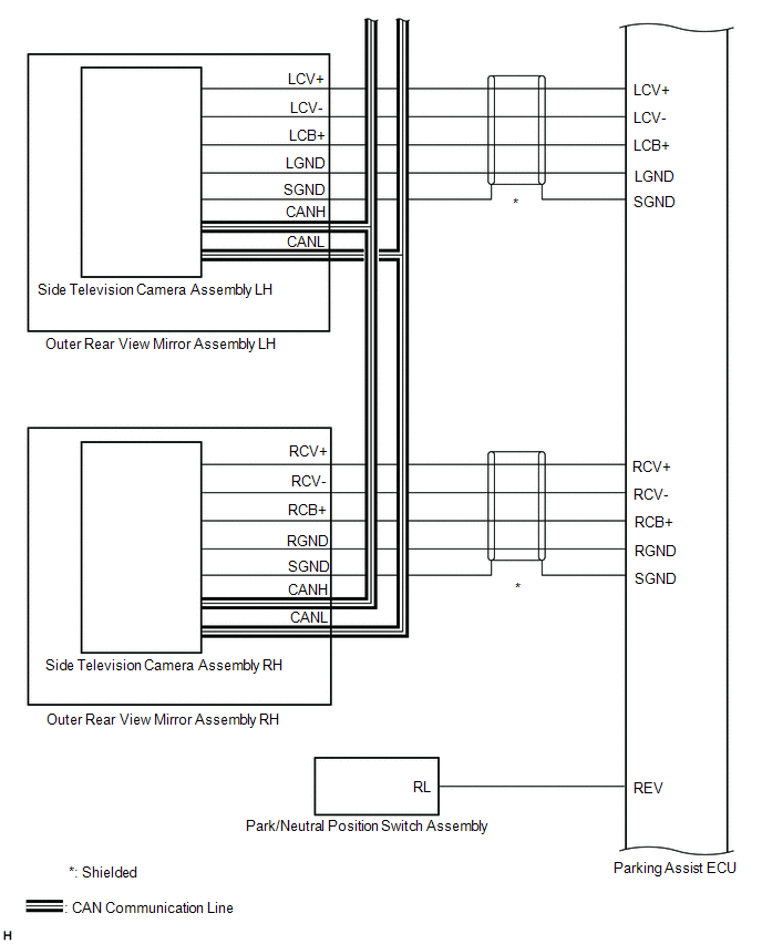
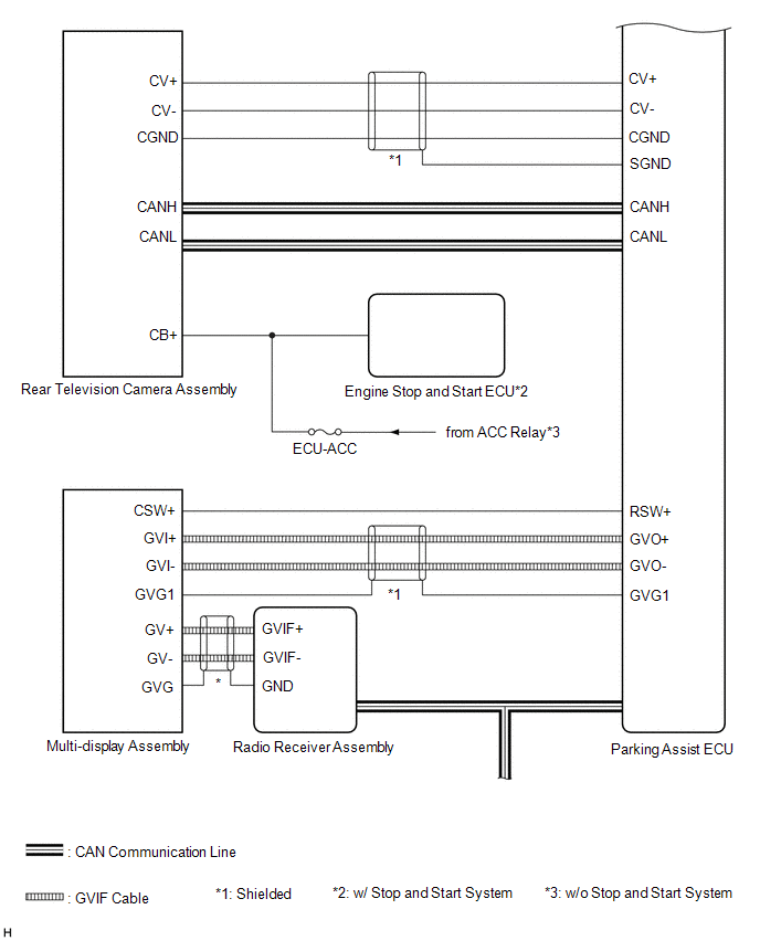
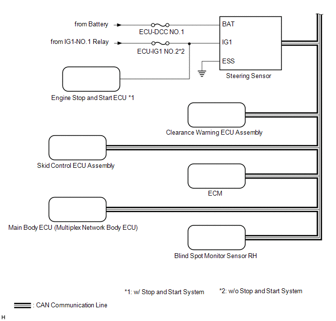
SYSTEM DIAGRAM
READ NEXT:
 Terminals Of Ecu
TERMINALS OF ECU PARKING ASSIST ECU (a) Disconnect the N44 parking assist ECU connector. (b) Measure the voltage and resistance according to the value(s) in the table below. Terminal No. (Symbol)
Lost Communication with Panoramic View Monitor Control Module (U023B)
DESCRIPTION These DTCs are stored if there is a malfunction in the CAN communication system connected to the rear television camera assembly. HINT: If CAN communication system DTCs are stored, they ma
Control Module Communication Bus Off (U0073,U0100,U0126,U0129,U0140,U0163,U0233,U023B,U0265,U1110)
DESCRIPTION These DTCs are stored if there is a malfunction in the CAN communication system connected to the parking assist ECU. HINT: If CAN communication system DTCs are stored, they may also be sto
SEE MORE:
Wiper and Washer Switch Circuit
DESCRIPTION The condition of the windshield wiper switch assembly is detected and sent to the steering sensor in this circuit. WIRING DIAGRAM PROCEDURE 1. READ VALUE USING TECHSTREAM (a) Connect the Techstream to the DLC3. (b) Turn the power switch on (IG). (c) Turn the Techstream on. (d)
Freeze Frame Data
FREEZE FRAME DATA DESCRIPTION (a) Whenever a front radar sensor system DTC is stored, the millimeter wave radar sensor assembly stores the current vehicle state as Freeze Frame Data. CHECK FREEZE FRAME DATA (a) Connect the Techstream to the DLC3. (b) Turn the power switch on (IG). (c) Turn the Techs
© 2016-2026 Copyright www.lexguide.net
