Lexus ES: Switch Lights of Remote Touch Always Illuminate or cannot be Controlled Using Rheostat
DESCRIPTION
Power is supplied to the remote touch (remote operation controller assembly) illumination when the light control switch is in the tail or head position.
HINT:
- When the remote touch (remote operation controller assembly) is in self check mode, the switch illumination on the remote touch may remain on.
- If any illumination controlled by the rheostat switch has a malfunction such as an short to ground, the remote touch (remote operation controller assembly) switch illumination is affected and cannot be controlled by the rheostat switch.
WIRING DIAGRAM

CAUTION / NOTICE / HINT
NOTICE:
Inspect the fuses for circuits related to this system before performing the following procedure.
PROCEDURE
| 1. | CHECK ILLUMINATION CONTROLLED BY RHEOSTAT SWITCH |
(a) Perform the following procedure and check that the illumination controlled by the rheostat switch illuminates properly.
(1) If the vehicle is in a bright area, move it to a dark area.
HINT:
When the vehicle is in a bright area, the switch illumination may not turn on due to the auto dimmer function.
(2) If the light control switch is in the AUTO position, turn the switch to the tail or head position.
HINT:
If the light control switch is in the AUTO position, the switch illumination will not turn on unless the surrounding area is dark.
| Result | Proceed to |
|---|---|
| Any of the illumination controlled by the rheostat switch does not illuminate properly. | A |
| All of the illumination controlled by the rheostat switch illuminates properly. | B |
HINT:
The shift lever illumination and panel switch illumination are controlled by the rheostat switch. If either of these has a malfunction such as an open circuit, the switch illumination of the remote touch (remote operation controller assembly) is affected and cannot be controlled by the rheostat switch.
| B |  | GO TO STEP 3 |
|

| 2. | REPAIR OR REPLACE ILLUMINATION CONTROLLED BY RHEOSTAT SWITCH |
(a) Repair or replace the part with the malfunctioning illumination that is controlled by the rheostat switch.
| NEXT | | GO TO STEP 3 |
| 3. | CHECK SYMPTOMS |
| (a) Perform the following procedure, operate the rheostat switch again, and check if illumination brightness adjustment is possible (including adjustment of other devices such as the radio receiver assembly). (1) Check if the remote touch (remote operation controller assembly) is in self check mode. If it is, cancel self check mode. Click here HINT: When the remote touch (remote operation controller assembly) is in self check mode, the switch illumination on the remote touch (remote operation controller assembly) may remain on. (2) If the vehicle is in a bright area, move it to a dark area. HINT: When the vehicle is in a bright area, the switch illumination may not turn on due to the auto dimmer function. (3) If the light control switch is in the AUTO position, turn the switch to the tail or head position. HINT: If the light control switch is in the AUTO position, the switch illumination will not turn on unless the surrounding area is dark. |
|
.png)
| Result | Proceed to |
|---|---|
| Switch illumination cannot be adjusted (illumination for other devices can be adjusted). | A |
| Switch illumination cannot be adjusted (illumination for other devices also cannot be adjusted). | B |
| Switch illumination can be adjusted. | C |
| B | | GO TO METER / GAUGE SYSTEM |
| C | | END |
|
| 4. | REMOTE TOUCH (REMOTE OPERATION CONTROLLER ASSEMBLY) SELF CHECK (SWITCH ILLUMINATION CHECK) |
(a) Enter self-diagnostic mode.
Click here .gif)
| (b) Operate the remote touch screen diagonally from the upper left to the lower right and check that the brightness of the switch illumination changes. NOTICE: Since the remote touch screen may recognize a pinch in/out or flick operation if operated with 2 fingers, always use 1 finger to operate the remote touch screen in self-diagnostic mode. |
|
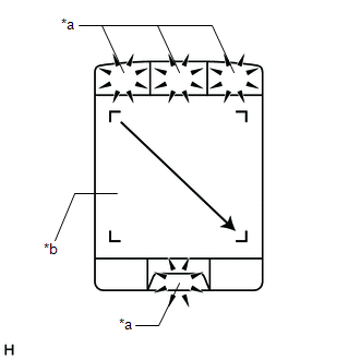
OK:
Brightness changes according to remote touch screen operation.
| NG | | REPLACE REMOTE TOUCH (REMOTE OPERATION CONTROLLER ASSEMBLY) |
|
| 5. | CHECK HARNESS AND CONNECTOR (ILLUMINATION SIGNAL CIRCUIT) |
(a) Disconnect the G56 remote touch (remote operation controller assembly) connector.
(b) Measure the voltage according to the value(s) in the table below.
Standard Voltage:
| Tester Connection | Condition | Specified Condition |
|---|---|---|
| G56-2 (ILL+) - Body ground | Power switch off Light control switch in tail or head position | 11 to 14 V |
| NG | | REPAIR OR REPLACE HARNESS OR CONNECTOR |
|
| 6. | CHECK HARNESS AND CONNECTOR (REMOTE TOUCH (REMOTE OPERATION CONTROLLER ASSEMBLY) - COMBINATION METER ASSEMBLY) |
(a) Disconnect the G56 remote touch (remote operation controller assembly) connector.
(b) Disconnect the G17 combination meter assembly connector.
(c) Measure the resistance according to the value(s) in the table below.
Standard Resistance:
| Tester Connection | Condition | Specified Condition |
|---|---|---|
| G56-5 (ILL-) - G17-39 (ILL-) | Always | Below 1 Ω |
| G56-5 (ILL-) or G17-39 (ILL-) - Body ground | Always | 10 kΩ or higher |
| OK | | REPLACE REMOTE TOUCH (REMOTE OPERATION CONTROLLER ASSEMBLY) |
| NG | | REPAIR OR REPLACE HARNESS OR CONNECTOR |
READ NEXT:
 Switch Lights of Remote Touch do not Illuminate
DESCRIPTION Power is supplied to the remote touch (remote operation controller assembly) illumination when the light control switch is in the tail or head position. WIRING DIAGRAM CAUTION / NOTICE /
Switch Operation of Remote Touch not Accepted
CAUTION / NOTICE / HINT NOTICE:
Depending on the parts that are replaced during vehicle inspection or maintenance, performing initialization, registration or calibration may be needed. Refer to Pre
System Description
SYSTEM DESCRIPTION NAVIGATION SYSTEM OUTLINE (a) Vehicle position tracking methods It is essential that the navigation system correctly tracks the current vehicle position and displays it on the map.
SEE MORE:
Parts Location
PARTS LOCATION ILLUSTRATION *1 FRONT DOOR COURTESY LIGHT SWITCH ASSEMBLY (for LH) *2 FRONT DOOR COURTESY LIGHT SWITCH ASSEMBLY (for RH) *3 SLIDING ROOF SWITCH (MAP LIGHT SUB-ASSEMBLY) *4 SLIDING ROOF ECU (SLIDING ROOF DRIVE GEAR SUB-ASSEMBLY) *5 COMBINATION METER ASSEMBLY
Precaution
PRECAUTION PRECAUTION FOR DISCONNECTING CABLE FROM NEGATIVE BATTERY TERMINAL NOTICE: When disconnecting the cable from the negative (-) battery terminal, initialize the following systems after the cable is reconnected. System Name See Procedure Lane Control System (for Gasoline Model)
