Lexus ES: Switch Lights of Remote Touch do not Illuminate
DESCRIPTION
Power is supplied to the remote touch (remote operation controller assembly) illumination when the light control switch is in the tail or head position.
WIRING DIAGRAM
.png)
CAUTION / NOTICE / HINT
NOTICE:
Inspect the fuse for circuits related to this system before performing the following procedure.
PROCEDURE
| 1. | CHECK SYMPTOMS |
| (a) Perform the following procedure and check the switch illumination again. (1) If the vehicle is in a bright area, move it to a dark area. HINT: When the vehicle is in a bright area, the switch illumination may not turn on due to the automatic dimmer function. (2) Set the rheostat to maximum brightness. HINT: If the brightness of the rheostat is set to low, switch illumination may not be recognized even when the switch illumination turns on. (3) If the light control switch is in the AUTO position, turn the switch to the tail or head position. HINT: If the light control switch is in the AUTO position, the switch illumination will not turn on unless the surrounding area is dark. OK: Switch illumination turns on. |
|

| OK | .gif) | END |
|

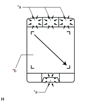
| 2. | REMOTE TOUCH (REMOTE OPERATION CONTROLLER ASSEMBLY) SELF CHECK (SWITCH ILLUMINATION CHECK) |
(a) Enter self-diagnostic mode.
Click here .gif)
| (b) Operate the remote touch screen diagonally from the upper left to the lower right and check that the brightness of the switch illumination changes. NOTICE: Since the remote touch screen may recognize a pinch in/out or flick operation if operated with 2 fingers, always use 1 finger to operate the remote touch screen in self-diagnostic mode. OK: Brightness changes according to remote touch screen operation. |
|
| NG | | REPLACE REMOTE TOUCH (REMOTE OPERATION CONTROLLER ASSEMBLY) |
|
| 3. | CHECK HARNESS AND CONNECTOR (ILLUMINATION SIGNAL CIRCUIT) |
(a) Disconnect the G56 remote touch (remote operation controller assembly) connector.
(b) Measure the voltage according to the value(s) in the table below.
Standard Voltage:
| Tester Connection | Condition | Specified Condition |
|---|---|---|
| G56-2 (ILL+) - Body ground | Power switch off Light control switch in tail or head position | 11 to 14 V |
| NG | | REPAIR OR REPLACE HARNESS OR CONNECTOR |
|
| 4. | CHECK HARNESS AND CONNECTOR (REMOTE TOUCH (REMOTE OPERATION CONTROLLER ASSEMBLY) - COMBINATION METER ASSEMBLY) |
(a) Disconnect the G56 remote touch (remote operation controller assembly) connector.
(b) Disconnect the G17 combination meter assembly connector.
(c) Measure the resistance according to the value(s) in the table below.
Standard Resistance:
| Tester Connection | Condition | Specified Condition |
|---|---|---|
| G56-5 (ILL-) - G17-39 (ILL-) | Always | Below 1 Ω |
| G56-5 (ILL-) or G17-39 (ILL-) - Body ground | Always | 10 kΩ or higher |
| NG | | REPAIR OR REPLACE HARNESS OR CONNECTOR |
|
| 5. | REPLACE REMOTE TOUCH (REMOTE OPERATION CONTROLLER ASSEMBLY) |
(a) Replace the remote touch (remote operation controller assembly) with a new or known good one.
Click here
(b) Check if the switch illumination turns on.
OK:
The switch illumination turns on when the light control switch is in the tail or head position.
| OK | | END |
| NG | | GO TO METER / GAUGE SYSTEM |
READ NEXT:
 Switch Operation of Remote Touch not Accepted
CAUTION / NOTICE / HINT NOTICE:
Depending on the parts that are replaced during vehicle inspection or maintenance, performing initialization, registration or calibration may be needed. Refer to Pre
System Description
SYSTEM DESCRIPTION NAVIGATION SYSTEM OUTLINE (a) Vehicle position tracking methods It is essential that the navigation system correctly tracks the current vehicle position and displays it on the map.
System Diagram
SYSTEM DIAGRAM w/ Parking Assist Monitor System w/ Panoramic View Monitor System w/o Manual (SOS) Switch w/ Manual (SOS) Switch w/ Manual (SOS) Switch for 10 Speakers for 17 Speakers for 17
SEE MORE:
DC/DC Converter Temperature Sensor 2 Circuit Short to Ground (P0E5811,P0E5815)
DESCRIPTION The motor generator control ECU (MG ECU), which is built into in the inverter with converter assembly, detects the temperature of the boost converter using the boost converter temperature sensor 2 (lower). The motor generator control ECU (MG ECU) also detects malfunctions in the boost co
Knock Sensor 1 Bank 1 or Single Sensor Circuit Short to Battery or Open (P032515)
DESCRIPTION Refer to DTC P032511. Click here HINT: When DTC P032515 is stored, the ECM enters fail-safe mode. During fail-safe mode, the ignition timing is delayed to its maximum retardation. Fail-safe mode continues until the power switch is turned off. DTC No. Detection Item DTC Detection
