Lexus ES: Operation Panel Disconnected (B15D9)
DESCRIPTION
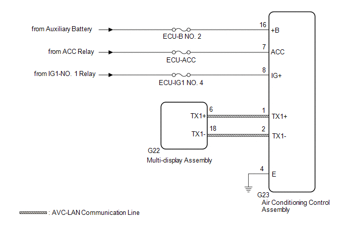
The air conditioning control assembly and multi-display assembly are connected by an AVC-LAN communication line. When an AVC-LAN communication error occurs between the multi-display assembly and air conditioning control assembly, these DTCs will be stored.
| DTC No. | Detection Item | DTC Detection Condition | Trouble Area |
|---|---|---|---|
| B15D9 | Operation Panel Disconnected | A device that is listed in the AVC-LAN connected device record of the master unit is missing. |
|
HINT:
The radio receiver assembly is the master unit.
WIRING DIAGRAM
CAUTION / NOTICE / HINT
HINT:
Inspect the fuses for circuits related to this system before performing the following procedure.
PROCEDURE
| 1. | CHECK DTC |
(a) If DTC B15D6 is output, perform troubleshooting for DTC B15D6 first.
| Result | Proceed to |
|---|---|
| DTC B15D6 is not output. | A |
| DTC B15D6 is output. | B |
| B | .gif) | GO TO DTC B15D6 |
|
.gif)
| 2. | CHECK OPTIONAL COMPONENTS (INCLUDING ASSOCIATED WIRING) |
(a) Check for optional components.
(1) Check that optional components (including associated wiring) which generate radio waves are not installed.
| Result | Proceed to |
|---|---|
| Optional components (including associated wiring) are installed. | A |
| Optional components (including associated wiring) are not installed. | B |
HINT:
- Electrical noise from radio waves generated by optional components or the wiring for those components may affect AVC-LAN communication.
- This DTC may be stored when an AVC-LAN communication error occurs due to electrical noise.
| B | | GO TO STEP 5 |
|
| 3. | REMOVE OPTIONAL COMPONENTS (INCLUDING ASSOCIATED WIRING) |
(a) Remove optional components (including associated wiring).
NOTICE:
Do not remove optional components or associated wiring without the permission of the customer.
|
| 4. | CHECK DTC |
(a) Clear the DTCs.
Body Electrical > Navigation System > Clear DTCs(b) Recheck for DTCs and check that no DTCs are output.
Body Electrical > Navigation System > Trouble CodesOK:
No DTCs are output.
| OK | | END (COMMUNICATION MALFUNCTION DUE TO NOISE) |
|
| 5. | CHECK HARNESS AND CONNECTOR (AIR CONDITIONING CONTROL ASSEMBLY POWER SOURCE) |
(a) Disconnect the G23 air conditioning control assembly connector.
(b) Measure the resistance according to the value(s) in the table below.
Standard Resistance:
| Tester Connection | Condition | Specified Condition |
|---|---|---|
| G23-4 (E) - Body ground | Always | Below 1 Ω |
(c) Measure the voltage according to the value(s) in the table below.
Standard Voltage:
| Tester Connection | Condition | Specified Condition |
|---|---|---|
| G23-16 (+B) - Body ground | Power switch off | 11 to 14 V |
| G23-7 (ACC) - Body ground | Power switch on (ACC) | 11 to 14 V |
| G23-8 (IG+) - Body ground | Power switch on (IG) | 11 to 14 V |
| NG | | REPAIR OR REPLACE HARNESS OR CONNECTOR |
|
| 6. | CHECK HARNESS AND CONNECTOR (AIR CONDITIONING CONTROL ASSEMBLY - MULTI-DISPLAY ASSEMBLY) |
(a) Disconnect the G23 air conditioning control assembly connector.
(b) Disconnect the G22 multi-display assembly connector.
(c) Measure the resistance according to the value(s) in the table below.
Standard Resistance:
| Tester Connection | Condition | Specified Condition |
|---|---|---|
| G23-1 (TX1+) - G22-6 (TX1+) | Always | Below 1 Ω |
| G23-2 (TX1-) - G22-18 (TX1-) | Always | Below 1 Ω |
| G23-1 (TX1+) or G22-6 (TX1+) - Body ground | Always | 10 kΩ or higher |
| G23-2 (TX1-) or G22-18 (TX1-) - Body ground | Always | 10 kΩ or higher |
| NG | | REPAIR OR REPLACE HARNESS OR CONNECTOR |
|
| 7. | CHECK AIR CONDITIONING CONTROL ASSEMBLY |
(a) Replace the air conditioning control assembly with a new or known good one.
Click here .gif)
(b) Clear the DTCs.
Body Electrical > Navigation System > Clear DTCs(c) Recheck for DTCs and check that no DTCs are output.
Body Electrical > Navigation System > Trouble CodesOK:
No DTCs are output.
| OK | | END |
| NG | | REPLACE MULTI-DISPLAY ASSEMBLY |
READ NEXT:
 Telematics Transceiver Disconnected (B15DB)
DESCRIPTION If the radio receiver assembly cannot detect the DCM (telematics transceiver) for a certain period of time (90 seconds) after the power switch is turned on (ACC) and the radio receiver ass
Air Conditioner ECU Vehicle Information Reading/Writing Processor Malfunction (B15F5)
DESCRIPTION This DTC is stored when items controlled by the air conditioning amplifier assembly cannot be customized via the audio and visual system vehicle customization screen. HINT: The air conditi
Main Body ECU Vehicle Information Reading/Writing Process Malfunction (B15F6)
DESCRIPTION This DTC is stored when items controlled by the main body ECU (multiplex network body ECU) cannot be customized via the audio and visual system vehicle customization screen. HINT: The main
SEE MORE:
FR Damping Force Control Actuator Circuit (C1731-C1734)
DESCRIPTION The absorber control actuator changes the damping force depending on absorber control ECU signals. DTC No. Detection Item DTC Detection Condition Trouble Area Warning Indicate Memory C1731 FR Damping Force Control Actuator Circuit Either condition is met:
An open
Open in Master Reservoir Level Switch Circuit (C120F)
DESCRIPTION DTC No. Detection Item INF Code DTC Detection Condition Trouble Area MIL Note C120F Open in Master Reservoir Level Switch Circuit 371 The brake fluid level warning switch (brake booster with master cylinder assembly) circuit is open for 2 seconds or more.
Op
