Lexus ES: Telematics Transceiver Disconnected (B15DB)
DESCRIPTION
If the radio receiver assembly cannot detect the DCM (telematics transceiver) for a certain period of time (90 seconds) after the power switch is turned on (ACC) and the radio receiver assembly confirms that the information is missing by checking past DCM (telematics transceiver) recognition information (registered information), this DTC will be stored.
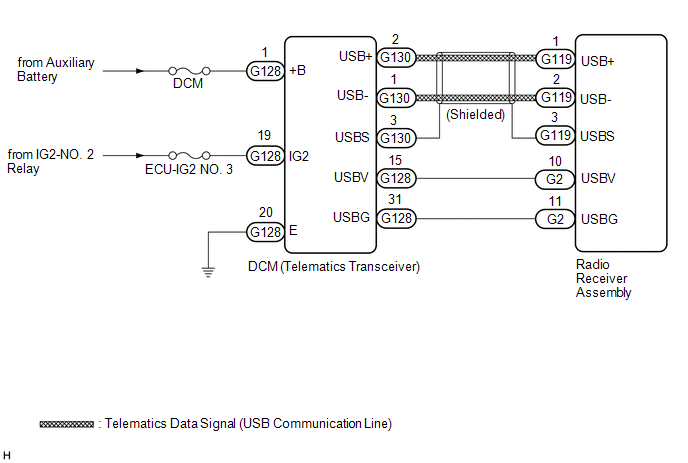
The telematics system uses USB communication between devices. If an open, short, short to +B or short to ground occurs in the USB circuit, communication is interrupted and the telematics system will not operate normally.
| DTC No. | Detection Item | DTC Detection Condition | Trouble Area |
|---|---|---|---|
| B15DB | Telematics Transceiver Disconnected | DCM (telematics transceiver) disconnected |
|
HINT:
This DTC may be stored due to environmental reasons such as electrical noise or interference.
WIRING DIAGRAM
CAUTION / NOTICE / HINT
NOTICE:
-
Depending on the parts that are replaced during vehicle inspection or maintenance, performing initialization, registration or calibration may be needed. Refer to Precaution for Audio and Visual System.
Click here
.gif)
-
When replacing the radio receiver assembly, always replace it with a new one. If a radio receiver assembly which was installed to another vehicle is used, the following may occur:
- A communication malfunction DTC may be stored.
- The radio receiver assembly may not operate normally.
- Inspect the fuses for circuits related to this system before performing the following procedure.
-
Before replacing the DCM (telematics transceiver), refer to Registration.
Click here
PROCEDURE
| 1. | CHECK HARNESS AND CONNECTOR (DCM (TELEMATICS TRANSCEIVER) POWER SOURCE) |
(a) Disconnect the G128 DCM (telematics transceiver) connector.
(b) Measure the resistance according to the value(s) in the table below.
Standard Resistance:
| Tester Connection | Condition | Specified Condition |
|---|---|---|
| G128-20 (E) - Body ground | Always | Below 1 Ω |
(c) Measure the voltage according to the value(s) in the table below.
Standard Voltage:
| Tester Connection | Condition | Specified Condition |
|---|---|---|
| G128-1 (+B) - G128-20 (E) | Power switch off | 11 to 14 V |
| G128-19 (IG2) - G128-20 (E) | Power switch on (IG) | 11 to 14 V |
| NG | .gif) | REPAIR OR REPLACE HARNESS OR CONNECTOR |
|
.gif)
| 2. | INSPECT RADIO RECEIVER ASSEMBLY |
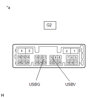
(a) Disconnect the G2 radio receiver assembly connector.
| (b) Measure the resistance according to the value(s) in the table below. Standard Resistance:
|
|
(c) Measure the voltage according to the value(s) in the table below.
Standard Voltage:
| Tester Connection | Condition | Specified Condition |
|---|---|---|
| G2-10 (USBV) - G2-11 (USBG) | Power switch on (IG) | 4.75 to 5.25 V |
| NG | | REPLACE RADIO RECEIVER ASSEMBLY |
|
| 3. | CHECK HARNESS AND CONNECTOR (RADIO RECEIVER ASSEMBLY - DCM (TELEMATICS TRANSCEIVER)) |
(a) Disconnect the G2 radio receiver assembly connector.
(b) Disconnect the G128 DCM (telematics transceiver) connector.
(c) Measure the resistance according to the value(s) in the table below.
Standard Resistance:
| Tester Connection | Condition | Specified Condition |
|---|---|---|
| G2-10 (USBV) - G128-15 (USBV) | Always | Below 1 Ω |
| G2-11 (USBG) - G128-31 (USBG) | Always | Below 1 Ω |
| G2-10 (USBV) or G128-15 (USBV) - Body ground | Always | 10 kΩ or higher |
| G2-11 (USBG) or G128-31 (USBG) - Body ground | Always | 10 kΩ or higher |
| NG | | REPAIR OR REPLACE HARNESS OR CONNECTOR |
|
| 4. | CHECK HARNESS AND CONNECTOR (RADIO RECEIVER ASSEMBLY - DCM (TELEMATICS TRANSCEIVER)) |
(a) Check the installation condition.
(1) Check the USB communication lines between the radio receiver assembly and DCM (telematics transceiver) for any installation or connection problems.
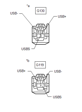
(b) Disconnect the G119 radio receiver assembly connector.
(c) Disconnect the G130 DCM (telematics transceiver) connector.
| (d) Measure the resistance according to the value(s) in the table below. Standard Resistance:
|
|
| NG | | REPAIR OR REPLACE HARNESS OR CONNECTOR |
|
| 5. | REPLACE DCM (TELEMATICS TRANSCEIVER) |
(a) Replace the DCM (telematics transceiver) with a new one.
Click here
(b) Clear the DTCs.
Body Electrical > Navigation System > Clear DTCs(c) Turn the power switch off.
(d) Turn the power switch on (IG) and wait for 90 seconds.
(e) Recheck for DTCs and check that no DTCs are output.
Body Electrical > Navigation System > Trouble CodesOK:
No DTCs are output.
| OK | | END |
| NG | | REPLACE RADIO RECEIVER ASSEMBLY |
READ NEXT:
 Air Conditioner ECU Vehicle Information Reading/Writing Processor Malfunction (B15F5)
DESCRIPTION This DTC is stored when items controlled by the air conditioning amplifier assembly cannot be customized via the audio and visual system vehicle customization screen. HINT: The air conditi
Main Body ECU Vehicle Information Reading/Writing Process Malfunction (B15F6)
DESCRIPTION This DTC is stored when items controlled by the main body ECU (multiplex network body ECU) cannot be customized via the audio and visual system vehicle customization screen. HINT: The main
Certification ECU Vehicle Information Reading/Writing Process Malfunction (B15F7)
DESCRIPTION This DTC is stored when items controlled by the certification ECU (smart key ECU assembly) cannot be customized via the audio and visual system vehicle customization screen. HINT: The cert
SEE MORE:
Components
COMPONENTS ILLUSTRATION *A for EGR Valve Bracket Connection Type *B for Cylinder Head Cover Sub-assembly Connection Type *1 FUEL DELIVERY PIPE *2 FUEL INJECTOR SEAL *3 DIRECT FUEL INJECTOR ASSEMBLY *4 NO. 1 FUEL PIPE SUB-ASSEMBLY *5 NO. 3 FUEL INJECTOR BACK-UP RIN
Components
COMPONENTS ILLUSTRATION *1 COWL SIDE TRIM BOARD LH *2 FRONT DOOR OPENING TRIM COVER LH *3 FRONT DOOR SCUFF PLATE LH *4 INSTRUMENT SIDE PANEL LH *5 LOWER INSTRUMENT PANEL FINISH PANEL SUB-ASSEMBLY *6 LUGGAGE DOOR OPENING SWITCH (TRUNK AND FUEL SWITCH ASSEMBLY) *7 N
