Lexus ES: Steering Wheel does not Heat Up When Heated Steering Wheel Switch is Pressed
DESCRIPTION
Click here .gif)
WIRING DIAGRAM
Click here
CAUTION / NOTICE / HINT
NOTICE:
The vehicle is equipped with a Supplemental Restraint System (SRS) which includes components such as airbags. Before servicing (including removal or installation of parts), be sure to read the precaution for Supplemental Restraint System.
Click here
PROCEDURE
| 1. | INSPECT STEERING WHEEL ASSEMBLY (THERMOSTAT, HEATER AND THERMISTOR) |
| (a) Disconnect the B heated steering wheel controller (steering vibration ECU) connector. |
|
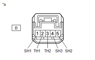
(b) Measure the resistance according to the value(s) in the table below.
Standard Resistance (for F SPORT Models):
| Tester Connection | Condition | Specified Condition |
|---|---|---|
| B-1 (SH1) - B-4 (SH3) | 20°C (68°F) | 2.52 to 3.00 Ω |
| B-1 (SH1) - B-5 (SH2) | 20°C (68°F) | 2.52 to 3.00 Ω |
| B-2 (TH1) - B-3 (TH2) | 10 to 30°C (50 to 86°F) | 4.228 to 8.701 kΩ |
Standard Resistance (except F SPORT Models):
| Tester Connection | Condition | Specified Condition |
|---|---|---|
| B-1 (SH1) - B-4 (SH3) | 20°C (68°F) | 2.33 to 2.77 Ω |
| B-1 (SH1) - B-5 (SH2) | 20°C (68°F) | 2.33 to 2.77 Ω |
| B-2 (TH1) - B-3 (TH2) | 10 to 30°C (50 to 86°F) | 4.228 to 8.701 kΩ |
| OK | .gif) | REPLACE HEATED STEERING WHEEL CONTROLLER (STEERING VIBRATION ECU) |
| NG | | REPLACE STEERING WHEEL ASSEMBLY |
READ NEXT:
 Precaution
PRECAUTION PRECAUTION FOR DISCONNECTING CABLE FROM NEGATIVE AUXILIARY BATTERY TERMINAL NOTICE: When disconnecting the cable from the negative (-) auxiliary battery terminal, initialize the following s
Parts Location
PARTS LOCATION ILLUSTRATION *1 SPIRAL CABLE SUB-ASSEMBLY *2 STEERING WHEEL HEATER SWITCH (REFRESHING SEAT SWITCH) *3 INSTRUMENT PANEL JUNCTION BLOCK ASSEMBLY - ECU-IG1 NO. 3 FUSE *4
SEE MORE:
Transmitter ID1 Error (C2141-C2144)
DESCRIPTION The tire pressure warning valve and transmitters that are installed in the tire and wheel assemblies measure the tire pressure of each wheel. The measured values are transmitted to the tire pressure warning ECU and receiver in the vehicle as radio waves. The ECU compares the measured tir
Active Noise Control ECU Communication Stop Mode
DESCRIPTION Detection Item Symptom Trouble Area Active Noise Control ECU Communication Stop Mode Any of the following conditions are met:
Communication stop for "Active Noise Control" is indicated on the "Communication Bus Check" screen of the Techstream.
Click here
Communicatio
