Lexus ES: Speed Sensor
Components
COMPONENTS
ILLUSTRATION
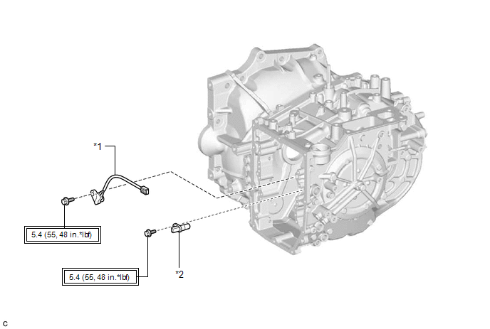
| *1 | TRANSMISSION REVOLUTION SENSOR (NC) | *2 | TRANSMISSION REVOLUTION SENSOR (NT) |
.png) | Tightening torque for "Major areas involving basic vehicle performance such as moving/turning/stopping": N*m (kgf*cm, ft.*lbf) | - | - |
Installation
INSTALLATION
PROCEDURE
1. INSTALL TRANSMISSION REVOLUTION SENSOR (NC)
(a) Install the transmission revolution sensor (NC) to the counter drive gear sub-assembly with the bolt.
Torque:
5.4 N·m {55 kgf·cm, 48 in·lbf}
2. INSTALL TRANSMISSION REVOLUTION SENSOR (NT)
(a) Install the transmission revolution sensor (NT) to the automatic transaxle case sub-assembly with the bolt.
Torque:
5.4 N·m {55 kgf·cm, 48 in·lbf}
3. INSTALL TRANSMISSION VALVE BODY ASSEMBLY
Click here .gif)
Removal
REMOVAL
CAUTION / NOTICE / HINT
The necessary procedures (adjustment, calibration, initialization or registration) that must be performed after parts are removed and installed, or replaced during transmission revolution sensor (NT) and transmission revolution sensor (NC) removal/installation are shown below.
Necessary Procedures After Parts Removed/Installed/Replaced| Replaced Part or Performed Procedure | Necessary Procedure | Effect/Inoperative Function when Necessary Procedure not Performed | Link |
|---|---|---|---|
| Replacement of transmission valve body assembly |
|
| |
| Replacement of automatic transaxle fluid | ATF thermal degradation estimate reset | The value of the Data List item "ATF Thermal Degradation Estimate" is not estimated correctly | |
PROCEDURE
1. REMOVE TRANSMISSION VALVE BODY ASSEMBLY
Click here .gif)
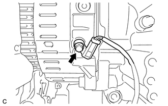
2. REMOVE TRANSMISSION REVOLUTION SENSOR (NT)
| (a) Remove the bolt and transmission revolution sensor (NT) from the automatic transaxle case sub-assembly. |
|
.png)
3. REMOVE TRANSMISSION REVOLUTION SENSOR (NC)
| (a) Remove the bolt and transmission revolution sensor (NC) from the counter drive gear sub-assembly. |
|
READ NEXT:
 Torque Converter And Drive Plate
InspectionINSPECTION PROCEDURE 1. INSPECT TORQUE CONVERTER ASSEMBLY (a) Inspect the one-way clutch. Press on the splines of the stator with a finger and rotate it. Check that it rotates smoothly when
Adjustment
ADJUSTMENT PROCEDURE 1. SECURE VEHICLE (a) Fully apply the parking brake and chock a wheel. CAUTION:
Make sure to apply the parking brake and chock a wheel before performing this procedure.
If th
SEE MORE:
Restraints Occupant Classification System Module Communication Stop Mode
DESCRIPTION Detection Item Symptom Trouble Area Restraints Occupant Classification System Module Communication Stop Mode Any of the following conditions are met:
Communication stop for "Occupant Detection" is indicated on the "Communication Bus Check" screen of the Techstream.
Click
Vehicle Speed Sensor "A" No Signal (P050031)
DESCRIPTION Vehicles, which are equipped with ABS (Anti-lock Brake System), detect the vehicle speed using the skid control ECU (brake actuator assembly) and speed sensor. The speed sensor monitors the wheel rotation speed and sends a signal to the skid control ECU. The skid control ECU converts the
